


Chapter 5.0: Installation
5.1: After unpacking, visually inspect the brake assembly to ensure that damage has not occurred
during shipment and that there are no loose or missing parts.
5.2: Prepare the brake support structure and install the brake assembly subject to the following:
5.2.(a): Allow adequate clearance between the brake and adjacent obstructions to allow access
for adjustment and maintenance.
Brake shoe replacement requires space for complete withdrawal of the link arm pivot pins.
5.2.(b): Whether mounting a brake in a new or existing installation, the base mounting bolts need
a reasonable clearance in the base mounting holes to allow the brake to be aligned for full
contact between the brake linings and the wheel.
5.2.(c): Circumstances may determine the best order of installation for the brake and the wheel.
This may be due to the available space or handling facilities on site; generally the wheel is
installed first.
5.2.(d): Center the brake shoes across the width of the brake wheel. This avoids ridge formation
and the possible creation of a dangerous situation as the linings wear.
5.3: Alternatively, it may be necessary to introduce the brake to the brake wheel from one side of the
wheel. In this case partial dismantling of the brake may be required depending on the
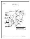
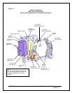
circumstances. Refer to the general arrangement and exploded view drawings in this manual to
evaluate the options.
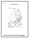
5.3.(a): After installing the brake and wheel, make preliminary adjustments to apply sufficient
shoe pressure to raise the actuator piston rod ½” above its fully retracted position.
5.3.(b): This will apply the brake at approximately rated torque, causing the brake to square itself
to the wheel and maximize the shoe contact area, providing the bolt hole clearance will permit.
5.3.(c): When the brake assembly is correctly aligned and clamped to the wheel, loosen each of
the securing bolts in turn and verify clearance in the base mounting holes. This will ensure
tolerance to allow minor adjustment to the brake alignment to accommodate future relined shoes.
5.3.(d): For the reason identified in the previous paragraph Magnetek does not recommend
“Dowelling” or “Keeper Plates” to maintain alignment.
5.4: Type MST/E brakes are generally installed with the base horizontal and the brake wheel shaft
horizontal.
5.5: In most applications the brake can be installed from one side of the brake wheel. Alternatively it
may be necessary to partially dismantle the brake.
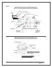
5.6: Type MST/E brakes can also be wall mounted, with the brake wheel shaft horizontal. This is only
possible if the actuator pump suction is flooded, which will be the case if the actuator hydraulic
section filler plug is at the highest point possible with the actuator horizontal. For this mounting
arrangement the actuator is best located above the wheel. The equalizing bolt opposite the
actuator will be most effective in ensuring equal shoe clearance.
8/17/2006 Page 14 of 33 MST/E Electric Shoe Brakes Manual
560022-R6