


Hydronic Heating Boilers and
Domestic Water Heaters
58
CLEANING AND
MAINTENANCE
Continued
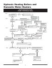
Adjusting Differential Air Pressure
The following is a recommended method for setting the
differential air pressure (ΔP) for each fan.
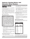
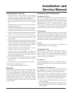
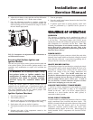
FIG. 56 Adjusting Air Shutter 399,999 - 750,000 Btu/hr
Models
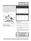
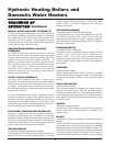
FIG. 57 Loosening Fan Transition Box Screws
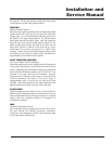
FIG. 58 Adjusting Air Shutter 990,000 - 2,070,000 Btu/hr
Models
Set Up Procedure
Beside each fan duct is an air pressure switch with a large and
a small tube delivering pressure from points inside the unit (see
FIG. 59). The pressure in the large tube is the chamber
pressure. The pressure in the small tube is the burner pressure.
They act together to make the pressure switch. By
disconnecting the caps from the tees in the pressure switch
hoses and connecting them to either side of a manometer, you
can read the differential pressure to the switch.
The “ (+)” connection on the manometer connects to the tee in
the tubing from the units front chamber and the “ (-) ”
connection on the manometer connects to the tee in the small
tubing from the burner.
If the air pressure switch does not make within 60 seconds
from the time the fans turn ON, the ignition module will go
into a soft lockout period (approximately five minutes in
duration) during which time the fans are turned OFF and the
module shows the Low Air flash code. If necessary, soft
lockout can be circumvented by cycling power to the ON/OFF
switch to cycle power to the unit.
Note: If the unit has been firing recently, allow the unit to cool
for five minutes with the fans running before beginning
the adjustment procedure.
Retain the plastic caps removed from the tees for
reinstallation when complete.
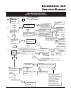
Adjustment Procedure
1. Remove the upper front jacket panels from the unit to
access the upper chamber.
2. Slightly loosen screws that attach fan transition box to
metal base (see FIG. 57).
3. Depending on model, the air shutter(s) may be located
either on the side or the rear of the fan duct. Locate the air
shutter at the side/rear of the fan duct (see FIG. 56 and 58).
Move the air shutter towards the rear or left side of the unit
to increase air pressure. Move the air shutter towards the
front or right side of the unit to decrease air pressure.
4a. On the 990,000 - 2,070,000 Btu/hr models adjust the air
shutter on the left fan until the differential pressure is
nominally 1.1 - 1.3 inches water column. Note: The air
chamber pressure is 1.2 inches water column for
liquefied petroleum (L.P.) and 1.4 inches water column
for natural.
4b. The 399,999 - 750,000 Btu/hr models have one fan with a
side mounted air shutter. The differential for these models
is nominally 1.5 - 1.65 inches water column.
5. Reattach the hoses to the pressure switch and locate the air
switch adjacent to the right fan and connect the tubes to
either side of your manometer.
MORE AIR
LESS AIR
AIR SHUTTER