


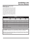
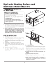
Hydronic Heating Boilers and
Domestic Water Heaters
38
INSTALLATION
Continued
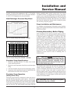
Boiler Flow Rate
If higher flow rates are required through the boiler, an optional
Cupro-Nickel heat exchanger is available. Consult the factory
for specific application requirements.
The heat exchanger is generally capable of operating within
the design flow rates of the building heating system. Should
the flow rate exceed the maximum allowable flow rate through
the boiler an external bypass must be installed. The bypass
should be fully sized with a balancing valve to allow for proper
adjustment of flow. Flow rate can be determined by measuring
the temperature rise through the boiler.
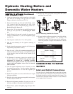
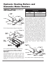
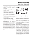
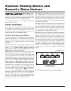
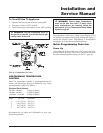
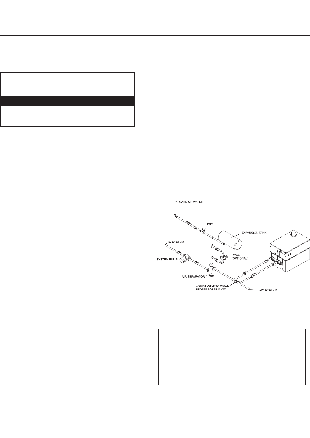
Boiler Bypass Requirements
The installer must ensure that the boiler is supplied with
adequate flow without excessive temperature rise. It is
recommended that this boiler be installed with a bypass in the
piping if the maximum recommended flow rate is exceeded.
The bypass will help to ensure that the boiler can be supplied
with adequate water flow. Flow rates exceeding the maximum
recommended flow will result in erosion of the boiler tubes. A
typical bypass with a valve as shown in FIG. 40 will allow
control of boiler flow.
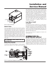
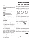
Temperature/Pressure Gauge
This boiler is equipped with a dial type temperature/pressure
gauge. This gauge is factory installed in the outlet side of the
heat exchanger. The gauge has one scale to read system
pressure and a separate scale to read water temperature in °F.
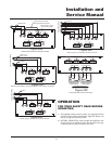
Placing the Boiler in Operation
Filling the System
All air must be purged from the system for proper operation.
An air scoop and air vent must be located close to the boiler
outlet and there should be a minimum distance between the
cold water feed and the system purge valve.
1. Close all drain cocks and air vents.
2. Open the makeup water valve and slowly fill the system.
3. If a makeup water pump is employed, adjust the pressure
to provide a minimum of 12 psi at the highest point in the
system. If a pressure regulator is also installed in the line,
it should be adjusted to the same pressure.
4. Close all valves. Purge one circuit at a time as follows:
A. Open one circuit drain valve and let the water drain for
at least five minutes. Ensure that there are no air bubbles
visible in the water stream before closing the drain valve.
B. Repeat this procedure for each circuit.
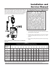
FIG. 40 Boiler Bypass Piping for High Flow Systems
5. Open all valves after all circuits have been purged. Make sure
there are no system leaks.
6. Run the system circulating pump for a minimum of
30 minutes with the boiler turned OFF.
7. Open all strainers in the system and check for debris.
8. Recheck all air vents as described in step 4.
ƽ CAUTION:
The maximum flow rate through
the boiler with a copper heat exchanger MUST
NOT exceed the following:
399,999 - 750,000 55 GPM
990,000 - 2,070,000 90 GPM
Input - Btu/hr Maximum Flow Rate
ƽ CAUTION: Do not use petroleum based
stop leak products. All system leaks must be
repaired. The constant addition of make-up
water can cause damage to the boiler heat
exchanger due to scale accumulation. Scale
reduces flow and heat transfer, causing
overheating of the heat exchanger.