


Hydronic Heating Boilers and
Domestic Water Heaters
26
INSTALLATION
Continued
You must locate the combustion air cap and the flue gas outlet
on the same roof top surface (vertical direct vent system) or
sidewall surface (horizontal direct vent system) and in the
same pressure zone as the vent termination. Follow all
clearance requirements listed on this page.
Purchase and assemble the combustion air inlet cap to protect
the air inlet from wind and weather.
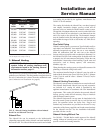
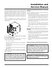
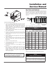
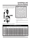
Alternatively, assemble the combustion air inlet cap for
vertical rooftop air inlet from items purchased locally. The air
inlet cap consists of two 90° elbows installed to the air inlet
pipe (see FIG. 26). Install the first 90° elbow on the rooftop at
the highest vertical point of the air inlet pipe. Install the second
90° elbow on the horizontal outlet of the first elbow. The outlet
of the second 90° elbow will be pointing down. You may use a
90° elbow and a 90° straight elbow to make this assembly. If
you use a straight piece of pipe between the two 90° elbows, it
should not exceed 6" (51mm) in length.
FIG. 26 Vertical Rooftop Air Inlet
For horizontal direct vent termination of combustion air, you
must use the termination cap from the appliance manufacturer.
The sidewall air inlet cap is available as part of a direct vent
kit. See TABLE–G, page 24 for Horizontal Direct Vent Kits.
Vertical Combustion Air Inlet Clearances
You must locate the air inlet termination elbow at least 12"
(30cm) above the roof or above normal snow levels.
If the air inlet cap is within a 10-foot (3.05m) radius of the flue
outlet, the point of termination for the combustion air inlet cap
must be at least 3 feet (0.91m) below the point of flue gas
termination (vent cap).
Do not install the combustion air inlet cap closer than 10 feet
(3.05m) from an inside corner of an L-shaped structure.
Horizontal Combustion Air Inlet Clearances
You must locate the horizontal air inlet termination point at
least 12" (30cm) above grade and above normal snow levels.
If the air inlet cap is within a 10-foot (3.05m) radius of the flue
outlet, the point of termination for the combustion air inlet cap
must be at least 3 feet (0.91m) horizontally and 12 inches
(30cm) below the point of flue gas termination (vent cap). Do
not install the horizontal combustion air inlet cap above the
flue outlet.
Do not install the combustion air inlet cap closer than 10 feet
(3.05m) from an inside corner of an L-shaped structure.
Multiple Sidewall Direct Vent Installations
The combustion air inlet caps for multiple appliance
installations must maintain the same minimum clearance from
the closest flue vent cap as specified in single appliance
installations. You may install multiple flue outlet caps side-by-
side and multiple combustion air inlet caps side-by-side, but
the air inlet must always be at least 3 feet (0.91m) horizontally
and 12 inches (30cm) below the closest flue outlet. Do not
install combustion air inlet caps above the flue outlets.
Maintain all clearances and installation requirements for
multiple appliance installations.
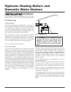
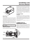
6. Outdoor Installation Venting
Units are self-venting and can be used outdoors when installed
with the optional outdoor cap. This cap mounts directly to the
top of the unit and covers the flue outlet and combustion air
inlet openings. No additional vent piping is required.
ƽ WARNING: Locate and install the
combustion air inlet termination correctly.
Failure to do so can allow the discharge of flue
products to be drawn into the combustion
process. This can result in incomplete
combustion and potentially hazardous levels of
carbon monoxide in the flue products. This will
cause operational problems and the spillage of
flue products. Spillage of flue products can
cause personal injury or death due to carbon
monoxide poisoning.
6" MAXIMUM
IMPORTANT: Before installing a venting system,
follow all venting clearances and requirements
found in the Venting, General Information
section, page 11.