Installation and
Service Manual
51
Ignition and Control Timings
Proven Pilot Hot Surface Ignition System M-9 on 990,000
through 2,070,000 Btu/hr models with two hot surface ignition
modules.
Hot Surface Ignition Module Timings (Nominal)
Prepurge:
15 Seconds
Hot Surface Igniter Heat-up Time:
25- 35 seconds
Main Burner Flame Establishing Period:
4 Seconds
Failure Response Time:
0.8 Seconds at less than 0.5 µA flame current
Flame Current:
5 - 15 µA
Time Delay Between Stages 1&2 and 3&4*:
15 Seconds
399,999 - 750,000 TIME DELAY stages 1 and 2 ONLY.
Note: Delay starts from the beginning of the ignition process.
In order to achieve a 15 second delay, a 60 second delay would
have to be programmed. Allow 45 seconds for the ignition
process.
Post-purge:
30 Seconds
Pump Delay Timing:
30 seconds minimum after burner shutdown up to a value of
ΔT MIN (adjustable from 1°F to 20°F)
* You can program a time delay of up to five minutes into the temperature controller. This
only applies to Mode 1 and Mode 2 operation. Mode 3 does not have any stage delay
capability. It is recommended, but not required, that the building control system have a
delay between the stages to allow time for the system temperature to settle before
additional stages are applied to the load. This will help prevent short cycling.
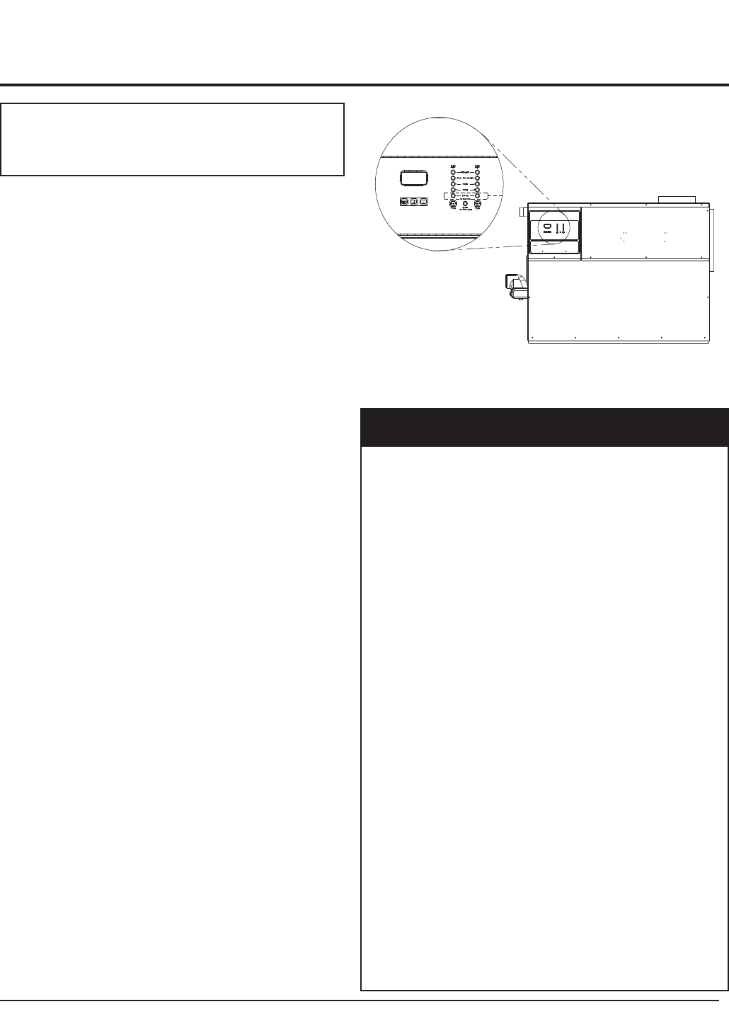
OPERATION AND DIAGNOSTIC
LIGHTS
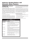
The control panel has up to 11 indicating and diagnostic lights
to show all major steps of operation and control sensed
malfunctions.
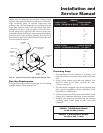
FIG. 53 Exterior Control Panel with
Operation/Diagnostic Lights and LCD Display
Code
Sequence Condition Lights
Prepurge 1 Operation of combustion
air fans before ignition on
stages 1 and 2.
Prepurge 2 Operation of combustion
air fans before ignition on
stages 3 and 4.
Trial for Ignition 1 Hot surface igniter 1
preparing to light
burners.
Trial for Ignition 2 (if equipped) Hot surface igniter 2
preparing to light burners.
Stage 1 On Burners for stage 1
operating.
Stage 2 On Burners for stage 2
operating.
Stage 3 On (if equipped) Burners for stage 3
operating.
Stage 4 On (if equipped) Burners for stage 4
operating.
Status 1 Remote status light
for ignition module #1.
Status 2 (if equipped) Remote status light for
ignition module #2.
Alarm Indicates flame failure on
either ignition module and
will indicate additional
alarms if the alarm on any
failure option is
purchased.
TABLE-V
Status LED Diagnostic Codes
ƽ CAUTION: Control panel is heavy and
awkward to handle when removed. Carefully
support the control panel when removing.


