Hydronic Heating Boilers and
Domestic Water Heaters
46
OPERATION
Continued
Scroll through the different settings by pressing the “Select”
button. Change settings by pressing either the “+” button or the
“–” button.
If no buttons are pushed after a few seconds, the control will
time-out and return to the “View” menu.
TABLE–Q, page 44 lists the Adjust Menu settings for the
different operation modes.
Access Levels
There are two levels of programming access for this
temperature control. These are the Advanced access level and
the User access level. The control is set to the Advanced access
level at the factory. You may wish to switch the control to the
User level, limiting the operator to certain basic programming
options. TABLE–Q shows the various menu settings for this
control. The items marked with an asterisk (*) indicate
adjustments only available in the Advanced access level.
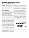
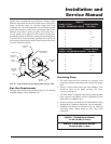
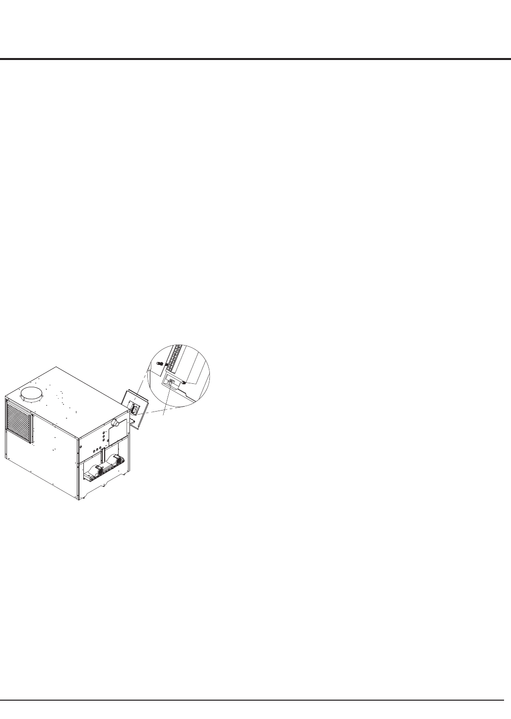
To switch from the Advanced access level to the User access
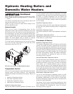
level, move the dip switch located on the back side of the
temperature control (see FIG. 49).
FIG. 49 User Access Level Dip Switch Location
Temperature Control
This is a four-stage temperature control that controls the burner
ignition, pump, and alarm functions. This temperature
controller can measure four different sensor inputs. They are as
follows:
1. Outside Air Temperature Sensor
2. Inlet Water Temperature Sensor
3. Outlet Water Temperature Sensor
4. Multi-Purpose Temperature Sensor
Outside Air Temperature Sensor
Only use this sensor for boiler operations. This allows you to
tie boiler operation to the outside air temperature. As outside
temperatures drop, the control will increase the temperature to
the boiler. As outside temperatures rise, the control will
decrease the temperature to the boiler. You can set the control
to shut the boiler off when a desired outside air temperature
level is reached.
Inlet Water Temperature Sensor
This sensor measures the inlet water temperature coming into
the unit. This is the default controlling sensor as shipped from
the factory.
Outlet Water Temperature Sensor
This sensor measures the outlet water temperature leaving the
unit.
Multi-Purpose Temperature Sensor
Depending on what mode the control is in, this sensor is either
a tank sensor or a system sensor.
Placement of Sensors
Outside Air Temperature Sensor
The outside air temperature sensor will only be used for boiler
systems. The outside air sensor is optional. You can purchase
the sensor from the appliance manufacturer. The sensor comes
with a housing that helps protect the sensor from the elements.
Mount the air sensor housing under the eve of the roof. Make
sure the housing is out of direct sunlight. This will ensure that
the sensor will accurately read the true outdoor temperature.
For more information on mounting the sensor, see Remote
Mounting of Sensors, page 48.
Inlet and Outlet Water Temperature Sensors
The inlet and outlet water temperature sensors are placed into
the inlet or outlet bulbwells on the boiler. These sensors are
installed by the factory in new units. If you have to reposition
these sensors, use a thermal-conductive paste to coat the
sensors. Insert the sensors in the appropriate bulbwell. Make
sure to insert the sensors all the way into the bulbwell, leaving
no air pocket between the front surface of the sensor and the
back of the bulbwell. Air pockets are thermally non-conductive
and will cause sensors to not read accurately.
Multi-Purpose Temperature Sensor
You can use the multi-purpose temperature sensor as a tank
sensor or as a system sensor. Install a bulbwell (provided by
the appliance manufacturer) in a water tank or a system loop.
Place the multi-purpose temperature sensor in the bulbwell to
monitor the water temperature.
Tank Sensor: This is used in water heating applications. Place
sensor in water storage tank to measure water temperature. For
more information on mounting the sensor, see Remote
Mounting of Sensors, page 48.
DIP SWITCH


