Hydronic Heating Boilers and
Domestic Water Heaters
34
INSTALLATION
Continued
1. Use only Type-T wire [63°F (35°C) rise] on all wiring
between the unit and field-installed devices.
2. Enclose line voltage wire exterior to the unit in approved
conduit or approved metal-clad cable.
3. The pump must run continuously when unit is being fired
(hot water heating boilers must use the optional pump
delay if the pump is to be cycled. See Freeze Protection,
page 7 when cycling the pump). Water heaters use the
pump delay as standard in accordance with ASHRAE 90.1
requirements.
4. To avoid serious damage, do not energize the unit until the
system is filled with water.
5. Provide the unit with proper overload protection.
BOILER SYSTEM PIPING
The drawings in this section show typical boiler piping
installations. Before beginning the installation, consult local
codes for specific plumbing requirements. Be sure to provide
unions and valves at the boiler inlet and outlet so it can be
isolated for service. You must install an air separation device in
the installation piping to eliminate trapped air in the system.
Locate a system air vent at the highest point in the system. The
system must also have a properly sized expansion tank
installed. Typically, an air charged diaphragm-type
compression tank is used. You must install the expansion tank
close to the boiler and on the suction side of the system pump
to ensure proper operation.
Provide suitable hangers or floor stands to support hot
water piping. The boiler alone should not support hot water
piping. Copper pipe systems are subject to considerable
expansion and contraction. Rigid pipe hangers could allow the
pipe to slide in the hanger resulting in noise transmitted into
the system. Use padding on rigid hangers installed with a
copper system. Pipe the boiler pressure relief valve to a
suitable floor drain. See the relief valve section in this manual.
General Plumbing Rules
1. Check all local codes.
2. For serviceability of boilers, always install unions.
3. Always pipe the pressure relief valve to an open drain.
4. Locate system air vents at the highest point of the system.
5. Expansion tank must be installed near the boiler and on
the suction side of the pump.
6. Support all water piping.
Water Connections: Heating Boilers Only
The 399,999 - 750,000 boilers have 2" NPT inlet and outlet
connections whereas the 990,000 - 2,070,000 boilers have
2 1/2" NPT inlet and outlet connections. Note: Field-installed
reducing bushings may decrease flow resulting in boiler noise
or flashing to steam.
Circulator Pump Requirements
This is a low mass, high efficiency hot water boiler which must
have adequate flow for quiet, efficient operation. Pump
selection is critical to achieve proper operation. A pump should
be selected to achieve proper system design water temperature
rise. A heat exchanger head-loss chart (FIG.’s 34 and 35) is
provided to assist in proper pump selection. Also provided is a
System Temperature Rise Chart (TABLE–P, page 37). This
table provides GPM and boiler head-loss at various
temperature rises for each boiler based on Btu/hr input.
Temperature rise is the difference in boiler inlet temperature
and boiler outlet temperature while the boiler is firing.
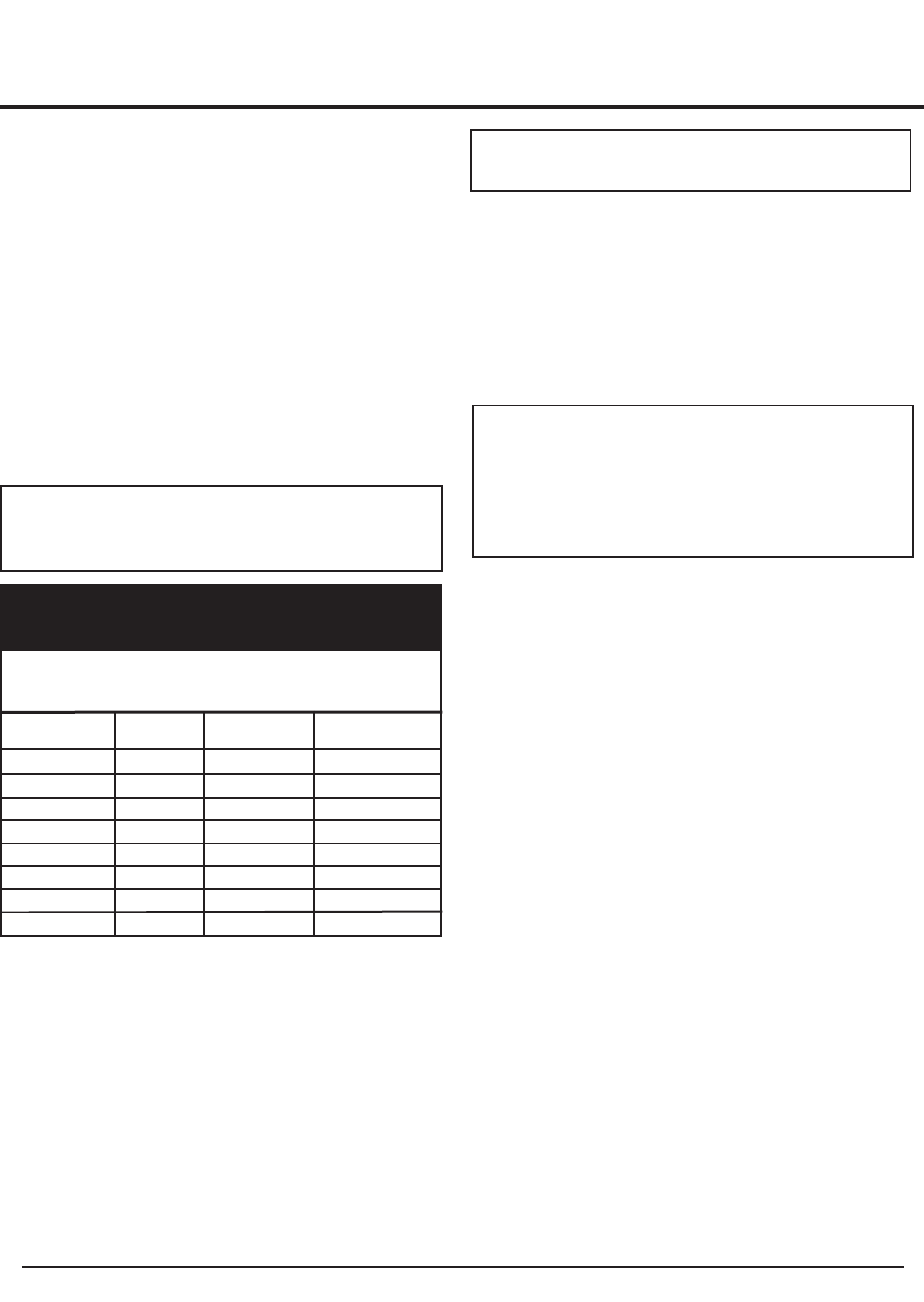
Btu/Hr Approximate
Input Controls Fans Total Amps
399,999 3.6 2.7 6.3
500,000 3.6 2.7 6.3
650,000 5.4 3.4 8.8
750,000 5.4 3.4 8.8
990,000 7.3 3.2 10.5
1,260,000 7.3 3.2 10.5
1,440,000 7.3 6.7 14.0
1,800,000 7.3 6.7 14.0
2,070,000 7.3 6.7 14.0
TABLE-N
AMP Draw Data
IMPORTANT: Do not block access to the
electrical cover plate when installing electrical
conduit.
ƽ CAUTION: This boiler system should not
be operated at less than 12 PSIG.
ƽ CAUTION: A leak in a boiler “system” will
cause the “system” to intake fresh water
constantly, which will cause the tubes to
accumulate a lime/scale build up. This will
cause a non-warrantable failure.