Installation and
Service Manual
57
Heat Exchanger Cleaning
1. While burners are removed, check the heat exchanger
surface for sooting. If present, heat exchanger must be
cleaned and problem corrected. Proceed as follows.
2. Remove gas manifold(s)/orifice assemblies as described in
steps 1 through 5 in Burner Removal and Cleaning, page
56.
3. Disconnect wiring from hot surface igniter(s) and hoses
from burner pressure taps.
4. Remove inner jacket panel mounting screws and slide door
assembly out toward front of the unit. Use caution to
prevent damage to the refractory and hot surface igniters.
5. Check “V” baffles and frame runners along front and back
edges of heat exchanger. Remove and clean if necessary.
6. Remove soot from heat exchanger with a stiff bristle brush.
Use a vacuum to remove loose soot from surfaces and
inner chamber.
7. The heat exchanger can be removed by sliding towards the
front of the unit. Once the heat exchanger is removed from
the unit, a garden hose can be used to wash the tubes to
ensure that all soot is removed from the heat exchanger
surfaces. Note: Do not wet the unit’s refractory.
8. Ensure that all burner ports are cleaned to remove any soot.
See Burner Removal and Cleaning, page 56.
9. Carefully reinstall the heat exchanger, “V” baffles, and
frame runners if removed from the unit. Note: Make sure
frame runners seal securely where they contact the front
and rear compartment refractory.
10. Carefully reinstall inner jacket panels, burners, manifolds,
wires and hoses. Use new gasket material to ensure a
proper air seal.
11. Reassemble all gas and water piping. Test for gas leaks.
12. Reassemble outer jacket panels.
13. Cycle unit and check for proper operation.
Electrical
This unit uses a transformer to supply a low voltage control
circuit. The voltage on the secondary side should be 24 to
28 VAC when measured with a volt meter. The 399,999 -
750,000 Btu/hr models have a 5 AMP circuit breaker provided
on the secondary side of the transformer and the 990,000 -
2,070,000 Btu/hr models have a 7 AMP circuit breaker
provided on the secondary side of the transformer. A tripped
circuit breaker indicates a short in the 24VAC controls that
must be corrected.
Combustion and Ventilation Air
Combustion Air Filter
This unit has a standard air filter located at the combustion air
inlet. This filter helps ensure clean air is used for the
combustion process. Check this filter every month and replace
when it becomes dirty. The filter size on the 399,999 - 750,000
Btu/hr models is 12" x 12" x 1" (30.5cm x 30.5cm x 2.5cm)
and 16" x 16" x 1" (40.6cm x 40.6cm x 2.5cm) on the 990,000
- 2,070,000 Btu/hr models. You can find these commercially
available filters at any home center or HVAC supply store.
Venting System
Examine the venting system at least once a year. Check more
often in the first year to determine inspection interval. Check
all joints and pipe connections for tightness, corrosion or
deterioration. Clean screens in the venting air intake system as
required. Have the entire system, including the venting system,
periodically inspected by a qualified service agency.
Air Flow
Check frequently to be sure the flow of combustion and
ventilation air to the unit is not obstructed.
Combustion Air Fans
Both the 399,999 - 750,000 Btu/hr models and the 990,000 -
2,070,000 Btu/hr models use a fan-assisted combustion
process. The 399,999 - 750,000 Btu/hr models have one fan
and the 990,000 - 2,070,000 Btu/hr models use two fans to
supply combustion air to the burners.
Fan Cleaning
Check each combustion air fan every six months. Clean fan as
required when installed in a dusty or dirty location. Oiling is
not required.
Combustion Air Fan Adjustment
The combustion air fans are factory pre-set and should not
need adjustment in most cases. Follow the steps below to
adjust the fan if a continuous Low Air status code occurs.
Note: On the 399,999 - 750,000 Btu/hr models the air shutter
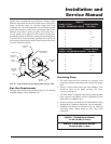
is adjusted on the side of the fan duct as depicted in FIG. 56.
On the 990,000 - 2,070,000 Btu/hr models the air shutter is
adjusted on the rear of the fan duct as depicted in FIG. 58.
1. Check for proper installation and draft in venting system.
Correct as required.
2. The following pressure settings are for installations up to
2000 feet altitude. Contact the factory for high altitude air
pressure settings.


