Installation and
Service Manual
39
9. Inspect the liquid level in the expansion tank. The system
must be full and under normal operating pressure to ensure
proper water level in the expansion tank. Ensure that
diaphragm type expansion tanks are properly charged and
not water logged.
10. Start the boiler according to the operating instructions in this
manual. Operate the system, including the pump, boiler and
radiation units, for one hour.
11. Recheck the water level in the expansion tank. If it exceeds
half the tank volume, open the tank to reduce the water level.
Recheck pressure charge on diaphragm type tanks.
12. Shut down the entire system and vent all radiation units and
high points in the system.
13. Close the water makeup valve and check the strainer and
pressure reducing valve for sediment or debris. Reopen the
water makeup valve.
14. Verify system pressure with the boiler pressure gauge before
beginning regular operation.
15. Within three days of startup, recheck and bleed all air vents
and the expansion tank using these instructions.
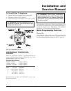
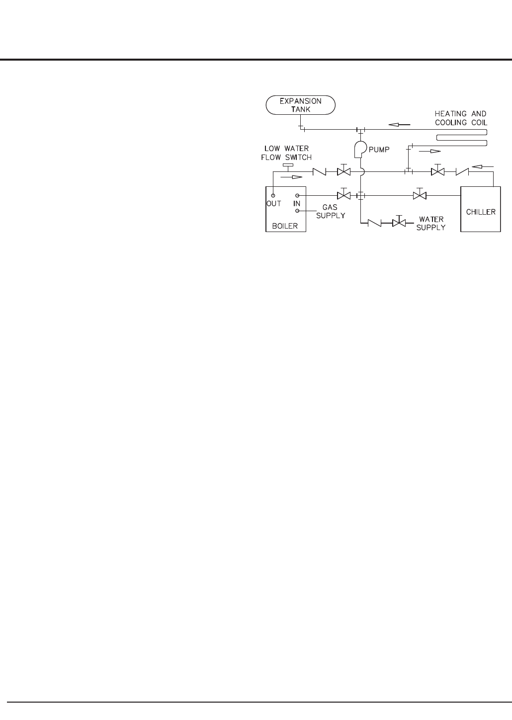
Installation with a Chilled Water
System
Pipe refrigeration systems in parallel. Install duct coil
downstream at cooling coil. Where the hot water heating boiler
is connected to a heating coil located in the air handling units
which may be exposed to refrigeration air circulation, the
boiler piping system must be equipped with flow control
valves or other automatic means to prevent gravity circulation
of the boiler water during the cooling cycle. The coil must be
vented at the high point and hot water from the boiler must
enter the coil at this point. Due to the fast heating capacity of
the boiler, it is not necessary to provide a ductstat to delay
circulator operation. Also, omit thermostat flow checks as the
boiler is cold when heating thermostat is satisfied. This
provides greater economy over maintaining standby heat (see
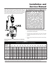
FIG. 41).
FIG. 41 Installation with a Chilled Water System
Boiler Operating Temperature Control
This unit can have up to four sensors. The four sensors are for
inlet temperature, outlet temperature, system/tank temperature,
or outdoor air temperature.
If the unit is ordered as a boiler without any options and you
need remote sensing, you can relocate either the inlet or outlet
sensors. For best performance, do not relocate the inlet or
outlet sensors. Install an optional system sensor.
If the unit is ordered as a water heater, the tank sensor is
included with the unit. Do not relocate the inlet or outlet
sensors from their bulbwells.
The digital electronic operating temperature control for these
units is located on the front control panel. The sensing
elements for the temperature control are placed in the inlet and
outlet bulbwells. See Remote Mounting of Sensors (Outdoor
Air Sensor), on page 48 of this manual. Carefully observe the
discharge water temperature on the initial boiler “ON” cycles.
The location of the temperature sensor will generally require a
lower temperature set point on the operating control to achieve
the desired discharge water temperature from the boiler. These
sensing element locations allow a boiler operating with a low
to moderate flow rate to sustain longer burner on cycles,
preventing short boiler “ON” cycles based on high discharge
water temperatures. For example, a boiler operating with a
180°F (82°C) discharge and a 20°F (11°C) temperature rise
would require approximately a 160°F (71°C) to 165°F (74°C)
set point with the temperature sensor installed on the inlet side
of the heat exchanger. The exact temperature set point is based
on your system’s requirements.


