Installation and
Service Manual
49
3. Do not locate temperature sensor wiring near electric motors.
4. Do not locate temperature sensor wiring near welding
equipment.
5. Make sure good mechanical connections are made to the
sensor, any interconnecting wiring and the controller.
6. Do not mount sensor with leadwire end pointing up in an area
where condensation can occur.
7. Use shielded wiring to connect the sensor to the control when
the possibility of an electrically noisy environment exist.
Shielded cable is recommended on all cable runs of more
than 25 feet in length.
Note: Ground the cable shield at the connection to the
boiler/electronic temperature control only. Do not ground the
shielded cable at the sensor end.
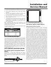
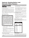
To maintain temperature accuracy, sensor wires should be at least
18 AWG. See Table T below.
Error and Warning Messages
The temperature control will enumerate errors on the display
when it senses any. If a sensor is shorted, the display will show
“SHr” and an identification of which sensor is effected. If a
sensor has an open circuit, the display will show “OPn” and an
identification of the sensor effected. If freeze protection is
active, the display will show “E02”. If the control read an error
at power-up, the display will show “E01” (simply turn the
power OFF and then ON again to reset the control). If ΔT
MAX is utilized and the outlet temperature exceeds this value,
the display will show “Err”.
HOT SURFACE IGNITION SYSTEM
Hot Surface Igniter and Ignition Control
Module
The 399,999 - 750,000 Btu/hr models have one ignition
module and one hot surface igniter. The 990,000 - 2,070,000
Btu/hr models have two ignition modules and two hot surface
igniters.
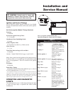
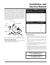
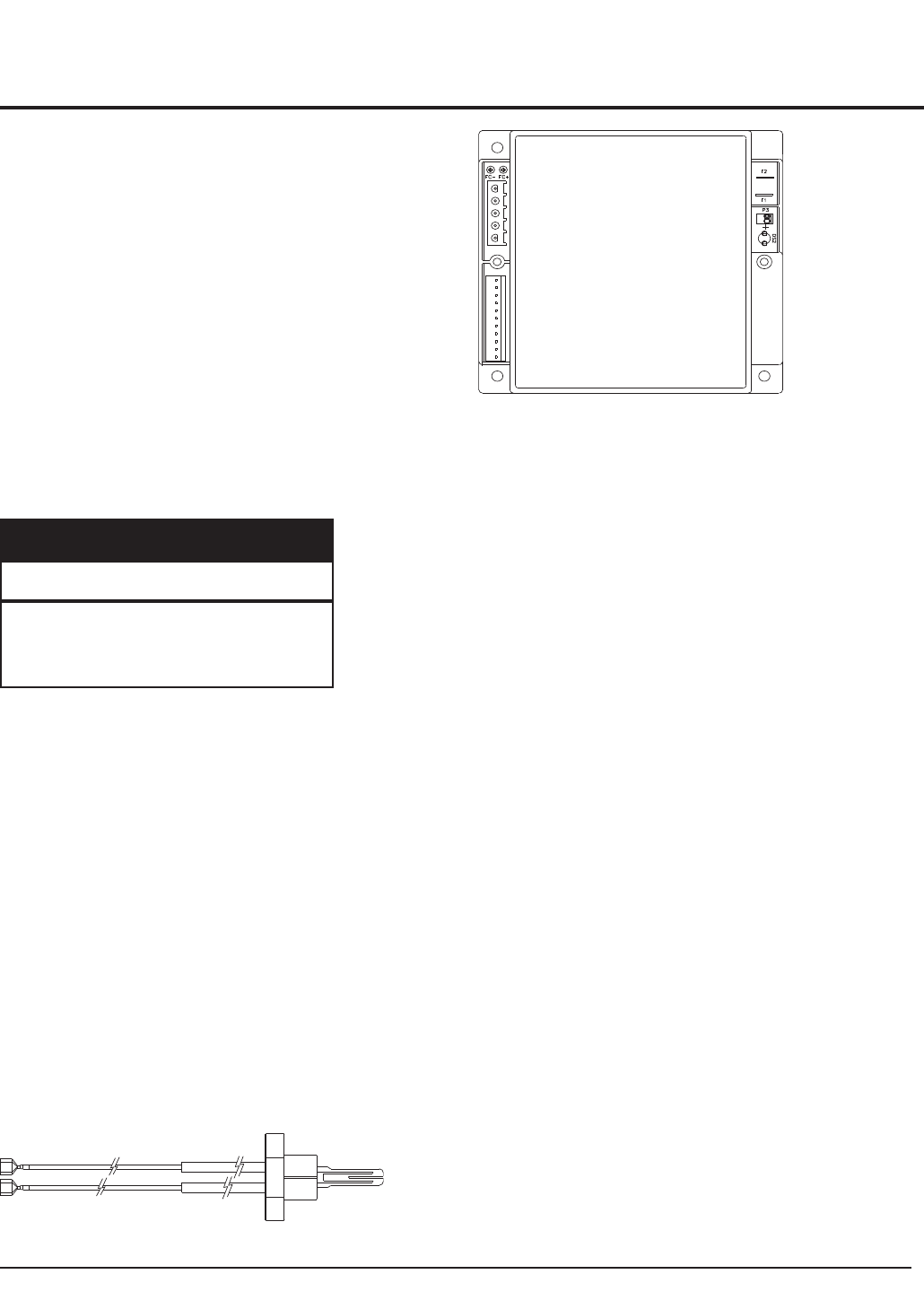
FIG. 51 Hot Surface Igniter
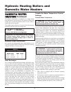
FIG. 52 Hot Surface Ignition Control Module
Hot Surface Ignition Control Module
Ignition Module Lockout Functions
The ignition module(s) may lockout in either a hard-lockout
condition, requiring pushing of the reset button to recycle the
control, or a soft-lockout condition which may recycle after an
approximate five-minute waiting period. This soft-lockout
condition is intended to allow self-correcting faults to correct
themselves and permit normal operation. A typical hard-lockout
fault is a flame failure condition. An ignition module that is in a
hard-lockout condition may only be reset by pushing the reset
button for the ignition control. The reset buttons are located on
the front of the control panel. Upon a flame failure, the reset
button is only active after the control module has completed its
post-purge cycle. Turning main power “OFF” and then “ON” or
cycling the thermostat will not reset a hard-lockout condition.
Wait five seconds after turning on main power before pushing the
reset button when the ignition module is in a hard lockout. The
ignition module will go into a soft lockout if conditions of low
air, low voltage or low hot surface igniter current. A soft-lockout
condition will operate the combustion air fans for the post purge
cycle and then the ignition module will pause for approximately
five minutes. At the end of this timed pause, the ignition module
will attempt a new trial for ignition sequence. If the soft-lockout
fault condition has subsided or has been corrected at the end of
the timed pause, main burner ignition should be achieved with
the resumption of the normal trial for ignition sequence. If the
control sensed fault is not corrected, the ignition module will
continue in the soft-lockout condition. If the electronic
thermostat opens during the soft-lockout period, the ignition
module will exit soft lockout and wait for a new call for heat from
the thermostat. A soft-lockout condition may also be reset by
manually cycling the electronic thermostat or turning the main
power switch “OFF” and then “ON” after the control sensed fault
has been corrected.
Wire Maximum
Gauge Allowable Length
12 GA 100 ft
14 GA 75 ft
16 GA 50 ft
18 GA 30 ft
TABLE-T
Remote Wire Connection


