


63
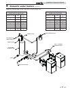
This section applies only to those appliances used to supply
domestic hot water, installed with a storage tank(s). A
circulating pump MUST be installed in the piping assembly to
the storage tank and valves used to control water velocity
through the appliance. Proper water velocity is important for
correct operation of your water heater.
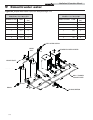
This section contains specific instructions for those appliances
used to supply domestic hot water. All warnings, cautions, notes
and instructions in the general installation and operation
sections apply to these instructions. Water heaters are designed
for installation with a storage tank. The operation of the
circulating pump, proper sizing of the piping between the tank
and heater and the control of water velocity, as explained in this
section, are important for correct operation of your water
heater.
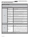
NOTICE
To ensure proper velocity through the heat
exchanger, it is necessary to regulate the
temperature rise across the heat exchanger
from inlet to outlet. This must be done on
initial installation and periodically
rechecked. With the correct temperature
rise across the heat exchanger when the
water heater is firing at 100% of rated input,
you may be assured of the proper velocity in
the tubes. This will yield long life and
economical operation from your water
heater.
Excessive lime/scale build-up in the heat
exchanger tubes is a result of restricted flow
and too little velocity in the tubes. Excessive
pitting or erosion in the tube is caused by
high water flow and too much velocity
through the tubes. Care should be taken to
measure temperature rise and maintain
velocity as follows:
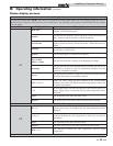
Initial set-up of maximum water flow
On initial start-up of the Power-fin the maximum water flow
through the heat exchanger must be manually set before normal
operation begins.
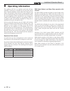
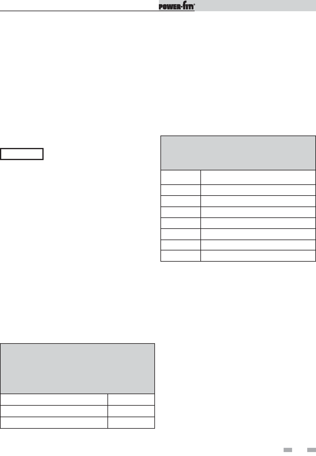
TABLE 9A
MAXIMUM WATER FLOW
ƽ CAUTION: The maximum flow rate through a Power-fin
water heater with a copper heat exchanger must be set to
provide and not exceed the following flow:
Model Maximum Flow
502, 752, 1002, and 1302 75 GPM
1501 - 1701 - 2001 90 GPM
If higher flow rates are required through the water heater, an
optional Cupro Nickel heat exchanger is available. Consult the
factory for specific application requirements.
The heat exchanger is capable of operating within the design
flow rates required for the water heater, storage tank(s), and
connecting piping. Erosion of the finned copper tubes may
occur if the flow rate exceeds the maximum allowable flow rate
through the water heater. The maximum flow rate through the
water heater must be adjusted. Maximum flow on Models 502 -
1302 is 75 GPM and 90 GPM on Models 1501 - 2001. Flow rate
can be determined by measuring the temperature rise through
the water heater when it is firing at full rate input.
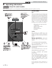
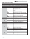
1. The pump must run continuously when the burner is
firing.
2. With the pump running and the burner in the water heater
in the off cycle, the inlet water temperature and outlet water
temperature readings on the Operator Interface should read
approximately the same temperatures. Water Temperature
Rise on the Operator Interface should read near zero.
3. Turn the water heater on and allow time for the temperature
to stabilize. The Service Mode can be used to force the water
heater to run at full fire. See the Power-fin Service Manual
for a detailed explanation of the Service Mode. Check the
water temperature rise in the Operator Interface when the
burner is firing at 100% of rated input.
4. Compare the water temperature rise in the Operator
Interface with the required temperature rise. Should
adjustment be needed, proceed as follows.
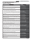
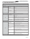
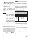
TABLE - 9B
TEMPERATURE RISE AT FULL RATE FIRE
75 AND 90 GPM FLOW
Model Temperature Rise
502 11°F (6.1°C)
752 17°F (9.4°C)
1002 23°F (12.8°C)
1302 30°F (16.7°C)
1501 28°F (15.6°C)
1701 32°F (17.8°C)
2001 38°F (21.1°C)
9 Domestic water heaters
Installation & Operation Manual