


32
Installation & Operation Manual
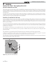
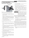
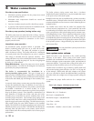
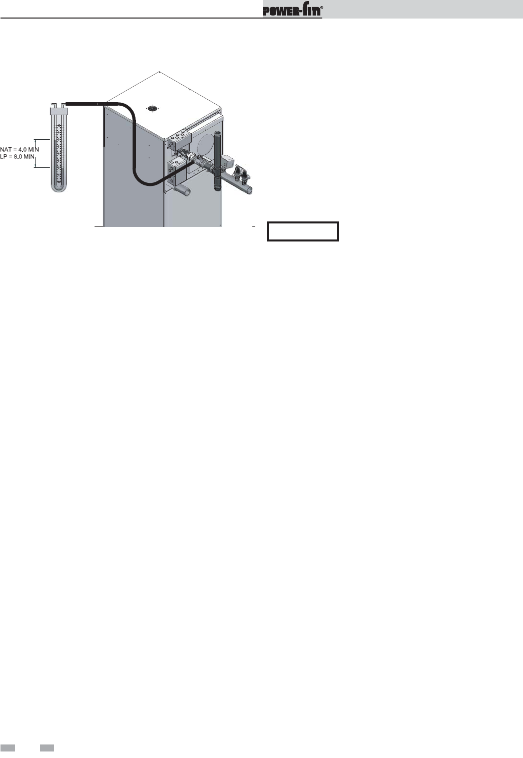
Figure 3-2_Gas Supply Pressure Measurement
14. Turn on the gas supply at the manual valve, turn on LP
gas at the tank if required.
15. Turn the power switch to the “ON” position.
16. Adjust the temperature set point on the display of the
SMART SYSTEM control module to the desired water
temperature so the appliance will call for heat.
17. Check burner performance by cycling the system while
you observe burner response. The burner should ignite
promptly. Flame pattern should be stable, see
“Maintenance - Normal Flame Pattern” in the Power-fin
Service Manual. Turn system off and allow burner to
cool, then cycle burner again to ensure proper ignition
and flame characteristics.
Checking gas supply pressure
1. Turn the main power switch to the “OFF” position.
2. Shut off the gas supply at the manual gas cock in the gas
piping to the appliance. If fuel supply is LP gas, shut off
gas supply at the tank.
3. Remove the 1/8" hex plug from the gas pressure test port
located on the manual shutoff valve at the rear of
the appliance. Install a fitting in the inlet pressure tapping
suitable to connect to a manometer or magnahelic gauge.
Range of scale should be 14 inches water column or
greater to check inlet pressure.
4. Turn on gas supply at the field installed manual gas cock,
turn on LP gas at tank if required.
5. Turn the power switch to the “ON” position.
6. Adjust the temperature set point on the display to call for
heat.
7. Observe the gas supply pressure as the burner fires at
100% of rated input. Percent of burner input will be
shown on the display of the SMART SYSTEM control
module.
8. Ensure inlet pressure is within specified range. Minimum
and maximum gas supply pressures are specified in the
Gas Supply section of this manual.
9. If gas pressure is out of range, contact the gas utility, gas
supplier, qualified installer or service agency to determine
necessary steps to provide proper gas pressure to the
control.
10. If gas supply pressure is within normal range, proceed to
remove gas manometer and replace pressure tap fittings
in the gas piping to the appliance.
11. Turn the power switch to the “OFF” position.
12. Shut off gas supply at the manual gas cock in the gas
piping to the appliance. If fuel supply is LP gas, shut off
gas supply at the tank.
13. Remove the manometer and related fittings from the
gas pressure test port at the inlet gas supply connection
to the appliance. Replace the 1/8" plug in the gas
pressure test port and tighten.
NOTICE
If a pressure drop of more than 2" w.c. occurs
between Standby (Static) Mode and
Operating (Dynamic) Mode, a gas volume
problem exists. Contact the gas utility, gas
supplier, qualified installer, or service agency
to determine the necessary steps to provide
the proper gas volume to the appliance.
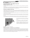
High and low gas pressure switches
1. Manual reset high and low gas pressure switches are
supplied to meet M13 firing code for Factory Mutual, GE
GAP, and CSD-1.
2. In the Commonwealth of Massachusetts, gas appliances
over 1,000,000 BTU must be equipped with manual reset
high and low gas pressure switches when required to meet
the Massachusetts requirements.
NOTE: Massachusetts code requires a pressure regulator to be
installed upstream of the low gas pressure switch. Lochinvar
requires any inline regulator used MUST BE of the lockup type
and be located a minimum of 10 feet from the appliance. Failure
to do so may result in insufficient gas volume supplied to the
appliance. Massachusetts also requires a shutoff valve be
installed ahead of the regulator for replacement or service.
When required, both regulator and shutoff valve are to be “field
provided”.
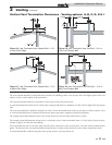
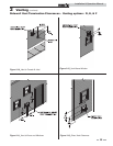
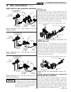
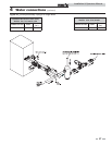
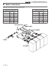
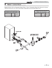
3. Figures 3-3A, B, and C on page 33 show piping connections
for high and low gas pressure switches for respective Power-
fin models.
3 Gas connections