


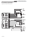
5 Electrical connections
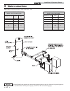
Boiler operating control module
The operating temperature control for the appliance is the
SMART SYSTEM control module. It is located on the inside of
the control panel, behind the front access door. Access to adjust
the temperature set point and other user adjustable points is
made through the Operator Interface located on the right front
access door. The outlet sensor is placed in a bulbwell installed
in the outlet side of the heat exchanger top header. The inlet
sensor is located in a bulbwell on the inlet side of the heat
exchanger top header.
The operating sensor, inlet or outlet, is selectable from the
screen in the Operator Interface.
The exact temperature set point is based on your system’s
requirements. Set the control set point(s) to the desired
operating water temperature.
The maximum temperature set point that can be programmed
into the standard control module from the Operator Interface
on a heating boiler is 220°F (104.4°C). The manual reset high
limit control for a heating boiler is adjustable up to a fixed
maximum setting of 230°F (110°C).
The maximum temperature set point for a water heater is 190°F
(88°C). The auto reset high limit is fixed at 200°F (93°C), and
the adjustable manual reset high limit has a maximum setting of
230°F (110°C).
A 120 VAC, 15 Amp, 1 ph, 60 Hz circuit is required for operation
of the appliance controls.
The appliance, when installed, must be electrically grounded in
accordance with the requirements of the authority having
jurisdiction or in the absence of such requirements, with the
latest edition of the National Electrical Code ANSI/NFPA No.
70. When the unit is installed in Canada, it must conform to the
CAE C22.1, Canadian Electrical Code, Part I and/or local
Electrical Codes. Multiple units connected in a Cascade must be
grounded to the same ground connection.
1. All wiring between the appliance and field installed devices
shall be made with type T wire [63°F (35°C) rise].
2. All line voltage wire exterior to the appliance must be
enclosed in approved conduit or approved metal clad
cable.
3. The circulating pump must run continuously when the
appliance is being fired.
4. To avoid serious damage, DO NOT energize the appliance
until the system is full of water. Ensure that all air is
removed from the heat exchanger and piping before
beginning initial operation. Serious damage may result if
the appliance is operated without proper flow.
5. Provide the appliance with proper overload protection.
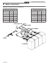
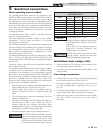
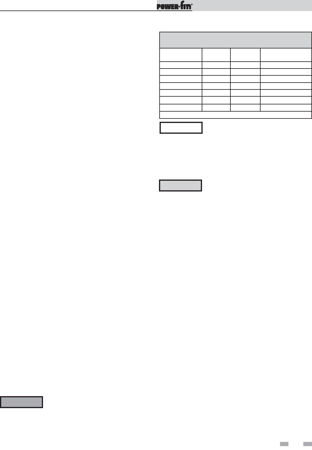
TABLE - 5A
AMP DRAW DATA
Model
Blower &
Controls
Pump FLA*
Approximate Total
Amps @ 120 VAC
502 6.7 8.8 15.5
752 6.7 8.8 15.5
1002 6.7 8.8 15.5
1302 6.7 8.8 15.5
1501 6.5 8.8 15.3
1701 6.5 8.8 15.3
2001 6.5 8.8 15.3
*Standard Pump Supplied with Water Heaters Only
ELECTRICAL SHOCK HAZARD – For your
safety, turn off electrical power supply before
making any electrical connections to avoid
possible electric shock hazard. Failure to do
so can cause severe personal injury or death.
Wiring must be N.E.C. Class 1.
If original wiring as supplied with the boiler
must be replaced, use only type 105°C wire or
equivalent.
Boiler must be electrically grounded as
required by National Electrical Code
ANSI/NFPA 70 – latest edition.
Label all wires prior to disconnection when
servicing controls. Wiring errors can cause
improper and dangerous operation.
ƽ WARNING
NOTICE
ƽ CAUTION
Installation must comply with:
1. National Electrical Code and any other national, state,
provincial, local codes, or regulations.
2. In Canada, CSA C22.1 Canadian Electrical Code Part 1, and
any local codes.
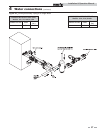
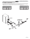
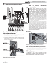
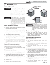
Line voltage connections
1. Connect 120 VAC power wiring to the line voltage terminal
strip in the junction box, as shown in FIG. 5-1.
2. Provide and install a fused disconnect or service switch
(15 AMP recommended) as required by the code (see
FIG. 5-1).
3. To activate a system pump, wire as shown in FIG. 5-1. If the
motor is larger than 1 HP, you must install a contactor.
4. When connecting power to units which are to be cascaded,
each unit must be connected to the same ground
connection.
43
Installation & Operation Manual