


33
Installation & Operation Manual
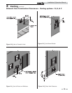
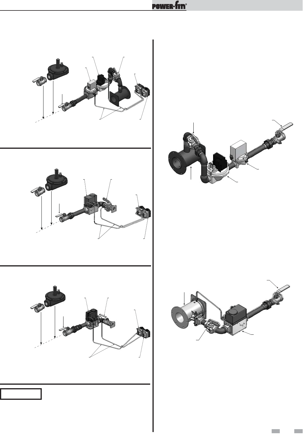
High and low gas pressure switches (continued)
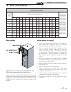
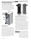
DOWNSTREAM
TEST VALVE
MANUAL SHUTOFF VALVE
VENTURI
COMBINATION VALVE
DIAPHRAM VALVE
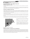
Figure 3-4_Gas Train Assembly F9 - Models 502- 1302
F9 gas train
The combination gas valve on this appliance uses line
(120 VAC) voltage for operation. These two valves satisfy the
requirement for the safety shutoff and operating valves
required on boilers and water heaters. The combination valve
also regulates the amount of gas mixed with the air delivered
to the burner for proper combustion. Both the combination
valve and diaphragm valve have threaded vents - see the
Venting of Gas Train Components section, this page.
There are no serviceable parts on the combination gas valve.
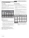
Venting of gas train components - F9/B9/M9 and
optional gas train components
Local codes may require the routing component bleeds and
vents to the atmosphere outside the building. Components
(valves, pressure switches) having vents which would require
external vent lines are provided with threaded vent line
connections. These vent line connection points may be accessed
by removing the top jacket panels. Proper routing of vent lines
to the atmosphere from the factory supplied termination points
is the responsibility of the installing contractor.
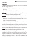
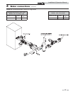
GAS COCK
REGULATING
GAS VALVE
GAS VALVE
BALL VALVE
W/PRESSURE TAP
ALUMINUM
TUBING
.25 X .03
HIGH GAS
PRESSURE
SWITCH
LOW GAS
PRESSURE
SWITCH
*SEE REGULATOR
INSTALLATION
NOTE ON PAGE 33
ROUTING MAY VARY
TYPICAL PRESSURE REGULATOR
STYLE MAY VARY FROM SHOWN
“FIELD PROVIDED”
(IF REQUIRED BY LOCAL CODES)
TYPICAL SHUTOFF
VALVE
“FIELD PROVIDED”
(IF REQUIRED BY LOCAL CODES)
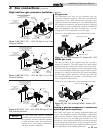
Figure 3-3A_PB/PF 502 - 1302 F9 High & Low Gas
Pressure Switches
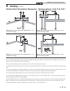
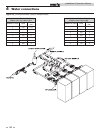
GAS
VALVE
BALL VALVE
W/PRESSURE TAP
GAS COCK
LOW
PRESSURE
SWITCH
HIGH
PRESSURE
SWITCH
ALUMINUM
TUBING
.25 X .03
*SEE REGULATOR
INSTALLATION
NOTE ON PAGE 33
ROUTING MAY VARY
TYPICAL PRESSURE REGULATOR
STYLE MAY VARY FROM SHOWN
“FIELD PROVIDED”
(IF REQUIRED BY LOCAL CODES)
TYPICAL SHUTOFF
VALVE
“FIELD PROVIDED”
(IF REQUIRED BY LOCAL CODES)
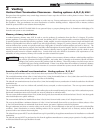
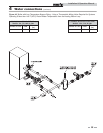
GAS VALVE
ALUMINUM
TUBING
.25 X .03
BALL VALVE
BALL VALVE
W/PRESSURE TAP
TYPICAL PRESSURE REGULATOR
STYLE MAY VARY FROM SHOWN
“FIELD PROVIDED”
(IF REQUIRED BY LOCAL CODES)
*SEE REGULATOR
INSTALLATION
NOTE ON PAGE 33
ROUTING MAY VARY
LOW
PRESSURE
SWITCH
HIGH
PRESSURE
SWITCH
TYPICAL SHUTOFF
VALVE
“FIELD PROVIDED”
(IF REQUIRED BY LOCAL CODES)
Figure 3-3B_PB/PF 502 - 1302 M9 High & Low Gas
Pressure Switches
Figure 3-3C_PB/PF 1501 - 2001 M9 & B9 High & Low
Gas Pressure Switches
NOTICE
The gas train and controls assembly
provided on this unit have been tested under
the applicable American National Standard
to meet minimum safety and performance
criteria such as safe lighting, combustion,
and safety shutdown operation.
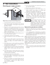
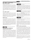
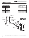
M9/B9 gas train
The ratio gas valve on this appliance uses line (120 VAC)
voltage for operation. The valve contains the safety shutoff
and operating valves required on boilers and water heaters.
The ratio valve uses the negative pressure signal generated by
the venturi to modulate the amount of gas, so that the proper
mixture of air and gas is delivered to the burner throughout
the full range of burner operation. The ratio gas valve does
not require installation of a vent line - see the Venting of Gas
Train Components section below.
There are no serviceable parts on the combination gas valve.
DOWNSTREAM
TEST VALVE
MANUAL SHUTOFF VALVE
VENTURI
RATIO VALVE
Figure 3-5_Gas Train Assembly M9/B9 - Models 1501
- 2001
3 Gas connections (continued)