


31
Installation & Operation Manual
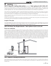
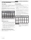
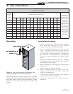
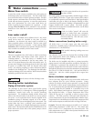
TABLE - 3C
GAS PIPING SIZE CHART
Nominal
Iron Pipe
Size
Inches
Length of Pipe in Straight Feet
Maximum
Capacity of Pipe
in Thousands of
Btu/hr per hour
for gas pressures
of 14 Inches
Water Column
(0.5 PSIG) or less
and a pressure
drop of 0.5 Inch
Water Column
(Based on NAT
GAS, 1025 Btu/hr
per Cubic Foot of
Gas and 0.60
Specific Gravity)
10 20 30 40 50 60 70 80 90 100 125 150 175 200
3/4 369 256 205 174 155 141 128 121 113 106 95 86 79 74
1 697 477 384 328 292 267 246 256 210 200 179 164 149 138
1 1/4 1,400 974 789 677 595 543 502 472 441 410 369 333 308 287
1 1/2 2,150 1,500 1,210 1,020 923 830 769 707 666 636 564 513 472 441
2 4,100 2,820 2,260 1,950 1,720 1,560 1,440 1,330 1,250 1,180 1,100 974 871 820
2 1/2 6,460 4,460 3,610 3,100 2,720 2,460 2,310 2,100 2,000 1,900 1,700 1,540 1,400 1,300
3 11,200 7,900 6,400 5,400 4,870 4,410 4,000 3,800 3,540 3,300 3,000 2,720 2,500 2,340
4 23,500 16,100 13,100 11,100 10,000 9,000 8,300 7,690 7,380 6,870 6,150 5,640 5,130 4,720
Gas piping
Install piping to control
1. The gas line should be a separate line direct from the
meter unless the existing gas line is of sufficient
capacity. Verify pipe size with your gas supplier.
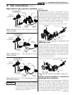
2. Use new, properly threaded black iron pipe free from
chips. If tubing is used, make sure the ends are
square, deburred and clean. All tubing bends must
be smooth and without deformation. Avoid flexible
gas connections. Internal diameter of flexible gas
lines may not provide appliance with proper volume
of gas.
3. Run pipe or tubing to the unit’s gas inlet. If tubing
is used, obtain a tube to pipe coupling in order to connect
the tubing to the unit’s gas inlet.
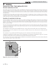
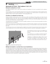
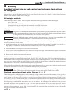
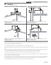
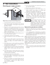
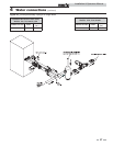
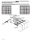
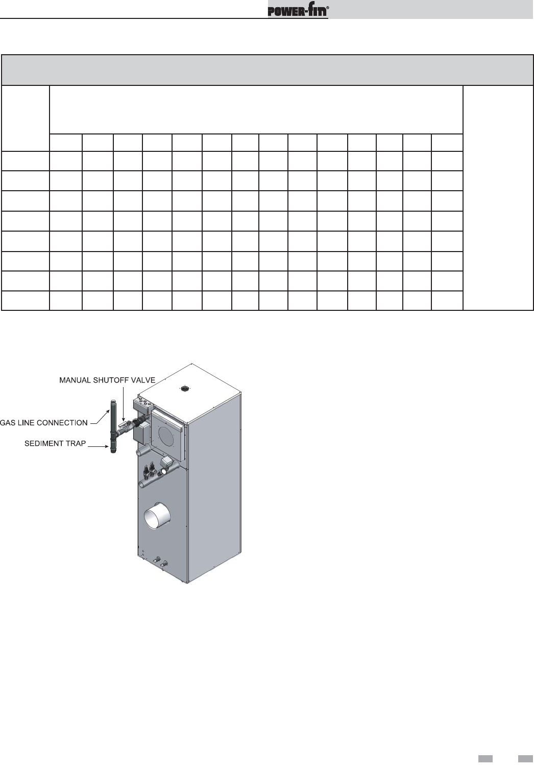
4. Install a sediment trap in the supply line to the unit’s gas
inlet (see FIG. 3-1).
5. Remove seal over gas inlet to the appliance.
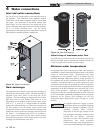
6. Apply a moderate amount of good quality pipe
compound (DO NOT use Teflon tape) to pipe only,
leaving two end threads bare.
7. Connect gas pipe to inlet of appliance. Use a wrench to
support the gas manifold on the appliance.
8. For LP gas, consult your LP gas supplier for expert
installation.
Figure 3-1_Gas Line Connection with Sediment Trap
(Drip Leg) and Manual Main Gas Shutoff Valve
All gas connections must be made with pipe joint compound
resistant to the action of liquefied petroleum and natural gas. All
piping must comply with local codes and ordinances. Tubing
installations must comply with approved standards and
practices.
3 Gas connections (continued)