


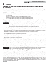
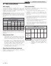
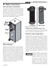
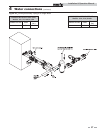
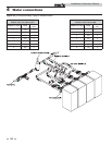
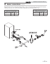
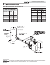
Figure 4-1_Water Connections
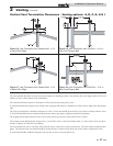
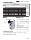
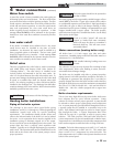
Heat exchanger
This appliance uses a finned copper tube heat exchanger to
maximize the heat transfer process. The heat exchanger is
mounted in the inner jacket on the front side of the
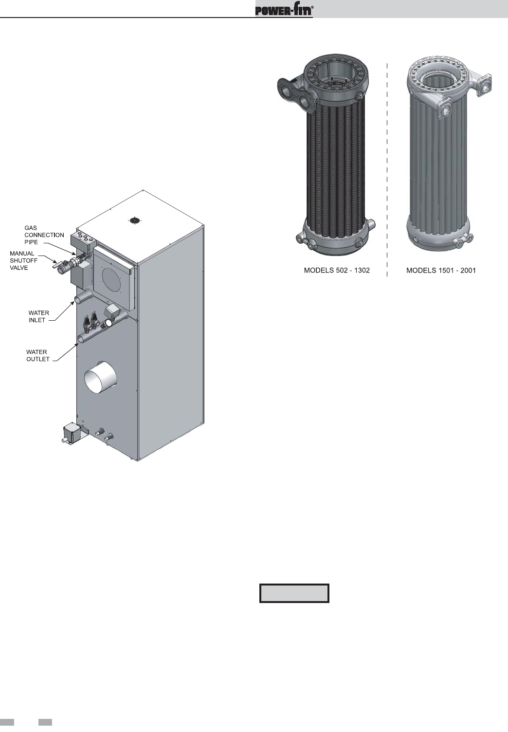
appliance. The heat exchanger is composed of two circular,
glass lined, and cast iron headers with either 20 or 24
(depending on the model) vertical finned copper tubes
(FIG. 4-2). A series of “V” shaped baffles are installed
between the individual tubes to control the movement of
the flue products over the finned copper surface and
increase heat transfer. Water enters the heat exchanger and
makes four passes over the area exposed to direct heat from
the burner. A circulating pump MUST be installed to
ensure proper water flow over the heat transfer surfaces
during burner operation. Water temperatures in the heat
exchanger are determined by water flow.
Figure 4-2_Heat Exchanger(s)
Initial set-up of maximum water flow
On initial start-up of the Power-fin, the maximum water flow to
the heat exchanger must be checked and manually limited with
a valve or bypass before normal operation begins.
Minimum water temperatures
A minimum return water temperature of 140°F (60°C) has been
established to control condensate formation based on the Btu/hr
output at rated burner input. Maintaining inlet water
temperatures to the appliance equal to or higher than the
specified minimum temperature ensures proper operation of
the appliance and prevents condensate formation on the heat
exchanger. An appliance allowed to sustain operation at water
temperatures lower than the specified minimum temperature
may not provide enough heat from the burner to maintain water
temperature in the heat exchanger above the 140°F (60°C) dew
point of flue products. Operation of the appliance at a
temperature below the specified minimum set point will result
in non-warrantable operational problems from the condensate
formation on the primary heat exchanger (see the Low
Temperature Bypass Requirements section on page 41 of this
manual).
ƽ CAUTION
An appliance allowed to operate at return
temperatures below the specified minimum
setting may experience problems with the
operating controls, safety switches,
obstruction of the flue gas passages on the
heat exchanger, incomplete combustion and
possible flue gas spillage. Sustained
operation at lower than specified water
temperatures may cause hazardous
conditions that may result in personal injury
or non-warrantable damage to the appliance.
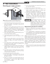
Inlet and outlet connections
For ease of service, install unions on the inlet and outlet of
the appliance. The connection to the appliance marked
“Water Inlet” on the header should be used for return from
the system. The connection on the header marked “Hot
Water Outlet” is to be connected to the supply side of the
system. Minimum water pipe connections to this appliance
are 2 1/2 inches (63.5mm) pipe. See the piping
requirements in the heating boiler or water heater section of
this manual for multiple appliance installations.
4 Water connections
34
Installation & Operation Manual