


Installation & Operation Manual
2 Venting (continued)
21
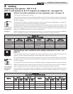
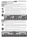
Common Venting CAT II:
Flues of multiple Power-fins may be combined by incorporating a vent increaser to change the Category IV appliance to a Category
II vent system which can be common vented using an engineered vent system. The increaser kit must be provided by the
manufacturer and the combined engineered vent system must be designed to ensure that flue products will be properly exhausted
from the building at all times. Failure to use the correct vent increaser or a properly sized vent system may result in a hazardous
condition where flue gases spill into an occupied living space. Consult a vent designer to determine the diameter of the common
vent pipe required for combined vent installation. It is recommended that all vent joints and seams are sealed gastight. This vent
system has specific vent material and installation requirements. The negative draft in a conventional vent installation must be
within the range of 0.02 to 0.08 inches w.c. to ensure proper operation. Make all draft readings while the unit is in stable operation
(approximately 2 to 5 minutes).
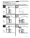
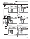
Common Venting CAT I - Venting options: G, H, & I (F9 / B9)
The negative draft in a conventional vent installation must be within the range of 0.02 to 0.08 inches w.c. to ensure proper operation.
Make all draft readings while the unit is in stable operation (approximately 2 to 5 minutes).
As noted in the diagrams on page 19, F9 models do not require a barometric damper in a single stack installation as illustrated.
However, common venting of multiple negative draft appliances requires that you MUST install a barometric damper on each unit
to regulate draft. Install per the requirements of the latest edition of the National Fuel Gas Code, ANSI Z223.1 and/or CAN/CGA-
B149 Installation Code.
Common Venting systems may be too large when an existing unit is removed. At the time of removal of an existing appliance, follow
the steps below with each appliance remaining connected to the common venting system placed in operation, while other appliances
remaining connected to the common venting system are not in operation:
a. Seal any unused opening in the common venting system.
b. Visually inspect the venting system for proper size and horizontal pitch and determine there is no blockage or restriction,
leakage, corrosion, and other unsafe condition.
c. Insofar as is practical, close all building doors and windows and all doors between the space in which the appliances
remaining connected to the common venting system are located and other spaces of the building. Turn on clothes dryers
and any other appliances not connected to the common venting system. Turn on any exhaust fans, such as range hoods
and bathroom exhausts, so they will operate at maximum speed. Do not operate a summer exhaust fan. Close fireplace
dampers.
d. Place in operation the appliance being inspected. Follow the lighting (operating) instructions in this manual (see page 51).
Adjust thermostat so appliance will operate continuously.
e. Test for spillage at the draft hood / relief opening after five (5) minutes of main burner operation. Use the
flame of a match or candle, or smoke from a cigarette, cigar, or pipe.
f. After it has been determined that each appliance remaining connected to the common venting system vents properly when
tested as above, return doors, windows, exhaust fans, fireplace dampers, and other gas burning appliances to their previous
conditions of use.
g. Any improper operation of the common venting system should be corrected so that the installation conforms to the latest
edition of the National Fuel Gas Code, ANSI Z223.1, in Canada, the latest edition of CGA Standard B149 Installation Code
for Gas Burning Appliances and Equipment.
When resizing any portion of the common venting system, the common venting system should be resized to approach the
minimum size as determined using the appropriate tables in the latest edition of the National Fuel Gas Code, ANSI Z223.1,
in Canada, the edition of CGA Standard B149 Installation Code for Gas Burning Appliances and Equipment.
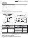
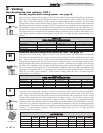
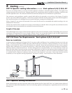
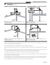
B9 Barometric Damper CAT I - Venting options: G, H, & I (Required for B9)
Category I B9 units require a field supplied barometric damper to be installed at the rear of the unit. The damper should be installed
directly after the flue collar prior to going vertical with the flue pipe as shown in the figures on page 19. The damper position
indicator should be visible after its installation. The damper should be sized appropriately for the flue pipe. 1501 B9 models require
a 12" damper. 1701 and 2001 B9 models require a 14" damper. When using barometric dampers, make-up air must be supplied to
the room in order for them to function. This location is important and specifically required for the B9 appliance and may not match
suggested locations found in the damper manufacturer’s installation manual. Otherwise follow the manufacturer’s
recommendations on damper installation and operation. The negative draft in a conventional vent installation must be within the
range of 0.02 to 0.08 inches w.c. to ensure proper operation. Make all draft readings while the unit is in stable operation
(approximately 2 to 5 minutes).
Note: Barometric dampers may also be required on 502, 752, 1002, and 1302 “F9” models for use in high draft areas and are required
when common venting multiple negative draft Category I appliances (see Common Venting CAT I section).