


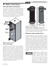
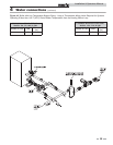


The boiler primary piping system must have a circulator
installed in the main system loop to carry the heated boiler water
to the point of use in the main system.
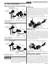
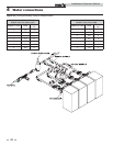
Multiple boilers may also be installed with a primary/secondary
manifold system. Multiple boilers should be connected to the
common manifold in reverse return to assist in balancing flow to
multiple boilers.
The installer must ensure that the boiler has adequate flow
without excessive temperature rise. Low system flow can result
in overheating of the boiler water which can cause short burner
cycles, system noise, relief valve discharge and in extreme cases,
a knocking flash to steam. These conditions indicate the need to
increase boiler flow to and from the boiler. This is generally
accomplished by either increasing the size of the boiler pump or
by increasing the diameter of the piping that connects the boiler
to the primary system. A larger diameter pipe reduces head loss
and increases flow.
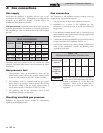
Circulator pump specifications
1. Maximum operating pressure for the pump must exceed
system operating pressure.
2. Maximum water temperature should not exceed the
nameplate rating.
3. Cast iron circulators may be used for closed loop systems.
4. A properly sized expansion tank must be installed near the
boiler and on the suction side of the pump.
Circulator pump operation (heating boilers only)
The boiler pump must run when the boiler is firing. Separate
supply circuits can be provided or the two circuits (pump and
controls) can be combined for connection to one circuit,
properly sized for both.
ƽ CAUTION
At no time should the system pressure be less
than 12 PSIG.
Intermittent pump operation
An intermittent pump operation feature is provided. The
boiler’s circulating pump will cycle on at each call for heat,
before the burner fires. The pump will continue to operate
while the burner is firing. The pump will run for a minimum
30 second period after the temperature set point is satisfied.
This timing is selectable from the Operator Interface. This
timing will remove any of the residual heat from the combustion
chamber before turning the pump off. See the wiring diagram
in Section 11 of this manual.
Pump Maintenance: Inspect the pump every six (6) months
and oil as necessary. Use SAE 30 non-detergent oil or lubricant
specified by the pump manufacturer.
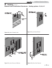
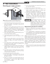
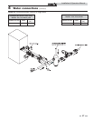
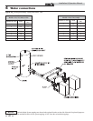
The boiler is recommended for installation in a
primary/secondary piping system. This type of system uses a
separate boiler circulating pump to supply flow to and from the
boiler only. The secondary pump is sized based on the head loss
of the boiler and related pipe and fittings in the secondary loop
only.
A properly sized primary system pump provides adequate flow
to carry the heated boiler water to radiation, air over coils, etc.
The fittings that connect the boiler to the primary system should
be installed a maximum of 12 inches (0.30m) (or 4 pipe
diameters) apart to ensure connection at a point of zero pressure
drop in the primary system. There should be a minimum of 10
pipe diameters of straight pipe before and after the boiler
secondary loop connections to prevent turbulent flow at the
secondary loop connections. The secondary loop piping to and
from the boiler must have a fully ported ball valve installed in
both the supply and return side piping. The ball valves must be
fully ported having the same inside diameter as the installed
piping. The ball valve in the piping supplying water to the boiler
will only be used as a service valve. The ball valve installed in the
discharge from the boiler back to the primary system will be
used to adjust boiler flow and temperature rise to ensure proper
performance.
Low system water volume
System run time is very important to the overall operating
efficiency of the boiler. Short cycling of the boiler creates
problems with condensation in the vent stack, condensation on
the heat exchanger, system temperature spikes, and mechanical
component failures. To prevent short cycling of the boiler, it is
important to limit the boiler cycles to six or fewer per hour.
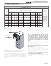
A buffer tank is an effective way to enhance a small system load
and increase heating system efficiency (see FIG. 4-6 on page 40
of this manual). Buffer tanks add water volume to the system
and act as a flywheel to absorb the additional Btu’s provided by
the boiler when only a single zone of a large system is calling for
heat.
To calculate the proper buffer tank size for a multiple zone
system:
(Run Cycle) (Output - Minimum System Load)
(Temp. Rise) (8.33) (60 Min.)
PBN2001-B9 ( 1.7:1 Turndown)
Min. Load = 100,000 Btu/Hr
Min. Boiler Output = 850,000 Btu/Hr
Cycle Time = 10 Min
Temp. Rise = 38
(10)(850,000 – 100,000) / (38)(8.33)(60) = 395 Gallons
4 Water connections
36
Installation & Operation Manual