


36
5 Electrical connections
Installation & Service Manual
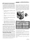
Temperature Control Sensors
This is a two-stage temperature control (M9/F9) that controls
the burner ignition and pump functions. This temperature
controller can measure up to three different sensor inputs,
depending upon how the unit is set up. They are as follows:
1. Inlet Water Temperature Sensor
2. Multi-Purpose Temperature Sensor
3. Outside Air Temperature Sensor
Inlet Water Temperature Sensor
This sensor measures the inlet water temperature coming into
the unit.
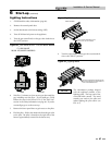
The inlet water temperature sensor is placed into the inlet
bulbwell on the boiler. This sensor is installed by the factory.
Multi-Purpose Temperature Sensor
Depending upon how your unit is set up, this sensor can be
used as a system sensor in a boiler system or a tank sensor for
water heater applications. Connect this sensor to the two blue
wires in the upper left-hand corner of the control panel.
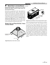
Outdoor Air Temperature Sensor
The outside air temperature sensor will only be used for
boiler systems. The outside air sensor is optional. This sensor
allows you to tie boiler operation to the outdoor air
temperature. As outside temperatures drop, the control will
increase the temperature setting of the boiler. As outdoor
temperatures rise, the control will decrease the temperature
to the selected set point of the boiler. You can set the control
to shut the boiler off when a desired outdoor air temperature
level is reached.
You must purchase the sensor from the appliance
manufacturer. The sensor comes with a housing that helps
protect the sensor from the elements. Mount the air sensor
housing outdoors, under the eve of the roof. Make sure the
housing is out of direct sunlight. This will ensure that the
sensor will accurately read the true outdoor temperature.
Connect the outdoor air temperature sensor to the terminal
block on the outdoor air reset board. For more information
on wiring the sensor, see Wiring of Remote Sensors, this page.
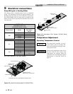
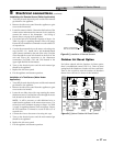
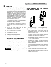
Installation of Remote Sensors
Make sure to insert the sensor all the way into the bulbwell,
leaving no air pocket between the front surface of the sensor
and the back of the bulbwell. Air pockets are thermally
non-conductive and will cause sensors to read inaccurately.
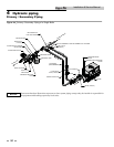
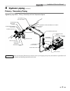
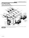
System Sensor
The system sensor must be installed when piping the boiler
in Primary - Secondary fashion when using the Pump Delay
option.
Tank Sensor
Water heaters are provided with an extra temperature
sensor that MUST be field installed. The sensor is shipped
loose in the I & O packet. This remote mounted sensor will
be the primary temperature sensor which will inform the
appliance’s built-in thermostat control. For domestic water
heating, the sensor MUST be installed into a bulbwell on
the storage tank. This is required to maintain the desired
temperature in the tank and reduce cycling of the heater.
In both applications be sure to insert the sensor all the way
into the bulbwell, leaving no air pockets between the front
surface of the sensor and the back of the bulbwell. Air
pockets are thermally non-conductive and will cause
sensors to read inaccurately.
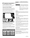
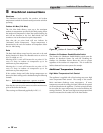
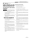
Wiring of Remote Sensors
To wire remote sensors, follow the guidelines below. Take
care to correctly wire sensors to the unit. Erratic
temperature readings can be caused by poor wiring
practices. Twist the wires between the unit and the remote
sensor. Turn wires at least three or four turns per linear foot
of wiring. This provides protection against some types of
electrical interferences.
1. Do not route temperature sensor wiring with building
power wiring.
2. Do not locate temperature sensor wiring next to control
contactors.
3. Do not locate temperature sensor wiring near electric
motors.
4. Do not locate temperature sensor wiring near welding
equipment.
5. Make sure good mechanical connections are made to
the sensor, any interconnecting wiring and the
controller.
6. Do not mount sensor with leadwire end pointing up in
an area where condensation can occur.
7. Use shielded wiring to connect the sensor to the control
when the possibility of an electrically noisy
environment exists. Shielded cable is recommended on
all cable runs of more than 25 feet in length.
NOTICE
Ground the cable shield at the
connection to the boiler temperature
control only. Do not ground the
shielded cable at the sensor end.
To maintain temperature accuracy,
sensor wires should be 18 AWG two
conductor (18/2). Use shielded wire if
required.