


53
Installation & Service Manual
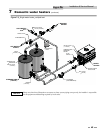
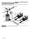
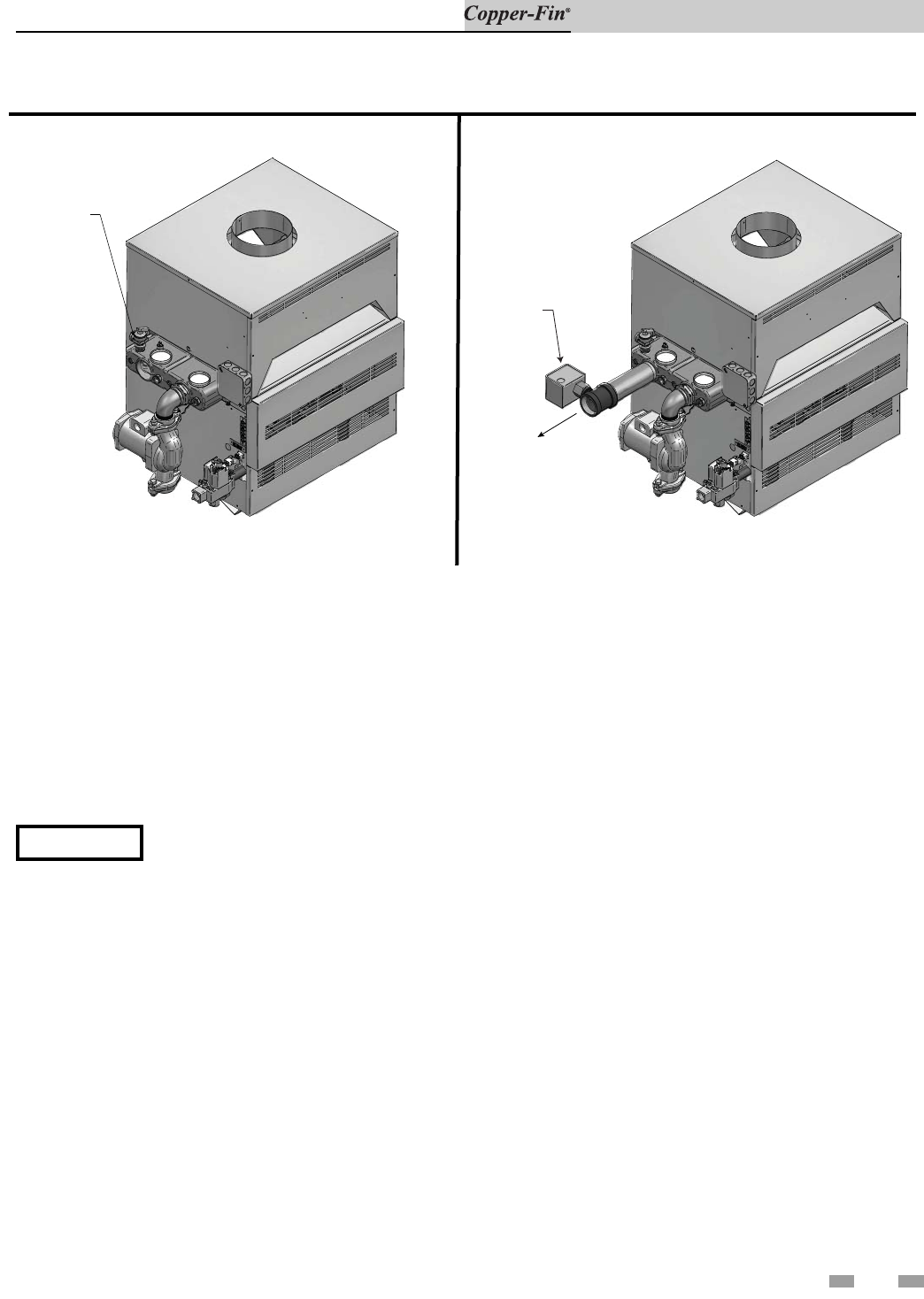
7 Domestic water heaters (continued)
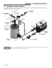
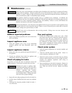
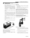
Figure 7-8_Relief Valve - Water heater
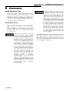
Figure 7-9_Water Flow Switch, Water heater
Relief Valve
RELIEF
VALVE
FLOW
SWITCH
FLOW
This appliance is supplied with a relief valve sized in
accordance with ASME Boiler and Pressure Ves sel Code,
Section IV (“Heating Boilers”). The re lief valve is mounted
directly into the heat ex chang er inside the header (see
FIG.’s 7-8 and 7-9). To pre vent water damage, the dis charge
from the relief valve shall be piped to a suit able floor drain for
disposal when relief occurs. No reducing couplings or other
restrictions shall be installed in the discharge line. The
discharge line shall allow complete drainage of the valve and
line. Relief valves should be manually operated at least once a
year.
ƽ CAUTION
Avoid contact with hot discharge water.
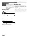
A water flow switch is available as a factory sup plied option
on all water heaters. The flow switch should be wired between
terminals X and B. Remove the jumper between the X and B
terminals on the terminal strip. This wiring connection
installs the flow switch in the 24 VAC safety cir cuit to prove
water flow before main burner ig ni tion. A flow switch
installed with the fac to ry sup plied minimum adjustment
setting requires a spe cif ic minimum flow to make the switch
and start burner operation. The flow rate required is a
function of the diameter of pipe and tee used for installation.
Ensure that the pump installed water heater will supply
adequate flow to make the flow switch con tacts and operate
the water heater.
Pressure Only Relief Valve
This water heater/hot water supply boiler is nor mal ly supplied
with a temperature and pressure re lief valve sized in accordance
with applicable codes. Units may be supplied with an optional
pres sure only relief valve. When a water heater/hot water supply
boil er equipped with this optional re lief valve is piped to a
separate storage vessel, the storage vessel must have a properly
installed tem per a ture and pressure relief valve which complies
with local codes.
Thermal Expansion
A relief valve which discharges periodically may be due to
thermal expansion in a closed system. A hot water supply boiler
installed in a closed sys tem, such as one with a backflow
preventer or check valve in stalled in the cold water supply, shall
be provided with means to control expansion. Con tact the
water sup pli er or local plumbing inspector on how to correct
this situation. Do not plug or cap the relief valve discharge!
Cathodic Protection
Hydrogen gas can be produced in a hot water sys tem that has
not been used for a long period of time (gen er al ly two weeks or
more). Hydrogen gas is ex treme ly flammable. To prevent the
pos si bil i ty of injury under these conditions, we rec om mend the
hot water faucet be open for several minutes at the kitch en sink
before you use any electrical ap pli ance which is connected to the
hot water sys tem. If hydrogen is present, there will be an
un usu al sound such as air escaping through the pipe as the hot
water begins to flow. There should be no smoking or open
flames near the faucet at the time it is open.
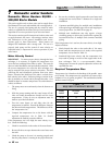
Water Flow Switch (if equipped)