


2 Venting (continued)
17
Installation & Service Manual
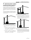
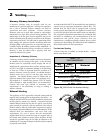
Masonry Chimney Installation
A masonry chimney must be properly sized for the
installation of a gas fired appliance. Venting of an appliance
into a cold or oversized masonry chimney can result in
op er a tion al and safety problems. Exterior masonry
chim neys, with one or more sides exposed to cold out door
tem per a tures, are more likely to have venting problems. The
temperature of the flue gases from an appliance may not be
able to suf fi cient ly heat the ma son ry structure of the chim ney
to generate proper draft. This will result in condensing of flue
gases, damage the masonry flue/tile, insufficient draft and
possible spill age of flue gases into an occupied living space.
Care ful ly in spect all chimney systems before installation. If
there is any doubt about the sizing or condition of a masonry
chimney, it must be relined with a prop er ly sized and
approved chimney liner system.
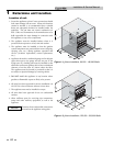
Inspection of a Masonry Chimney
A masonry chimney must be carefully inspected to determine
its suitability for the venting of flue gas es. A clay tile lined
chimney must be structurally sound, straight and free of
misaligned tile, gaps between liner sections, missing sections
of liner or any signs of con den sate drainage at the breaching
or clean out. If there is any doubt about the condition of a
masonry chimney, it must be relined. An unlined masonry
chimney must not be used to vent flue gases from this
appliance. An unlined chimney must be relined with an
approved chimney liner system when a new appliance is be -
ing attached to it. Metallic liner systems (Type “B” double
wall or flexible or rigid metallic liners) are recommended.
Consult with local code officials to determine code
requirements or the advisability of using or relining a
masonry chimney.
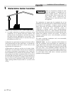
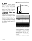
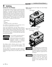
Sidewall Venting
This appliance is NOT approved for sidewall venting with the
negative draft venting system as shipped from the factory. An
induced draft fan MUST be used if the installation requires that
the flue gases be vented out a sidewall. A properly sized and
in stalled induced draft fan may also be used to vent the flue
gases ver ti cal ly if required by job site conditions. The induced
draft fan must be listed by a nationally recognized test agency,
be properly sized and installed per the rec om men da tions of the
in duced draft fan manufacturer and meet local code
requirements. Use care to ensure that the me chan i cal ly
supplied draft does not exceed the range of a negative 0.02 to
0.05 inches water column to ensure proper operation. If draft
exceeds the spec i fied range, the fan must be adjusted or the
installation of a baro met ric damper in the flue may be required
to prop er ly control draft.
An induced draft fan MUST be interlocked into the appliance’s
control circuit to start when the appliance calls for heat. The
in duced draft fan MUST also be equipped with a prov ing
switch, properly interlocked into the ap pli ance’s con trol circuit
to prove fan operation before the main burn ers are allowed to
fire. A vertical or sidewall vent termination for an induced draft
fan MUST be in stalled per the recommendations of the fan
manufacturer and provide proper clearances from any
combustion or ventilation openings, win dows, doors or other
open ings into the building. All induced draft fan in stal la tions
must comply with local code requirements.
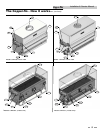
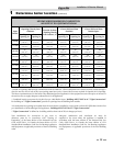
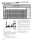
TABLE - 7B
VENT MATERIALS
Kit
Number
Input
Btu / hr
Material
KIT3104
90,000 CPVC Rated
135,000 CPVC Rated
Minimum Vent Length = 12 Equivalent Feet *
(ALL UNITS)
Maximum Vent Length = 25 Equivalent Feet * *
(ALL UNITS)
*Equivalent Feet: 90° Elbow = 5 Feet
45° Elbow = 3 Feet
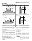
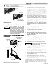
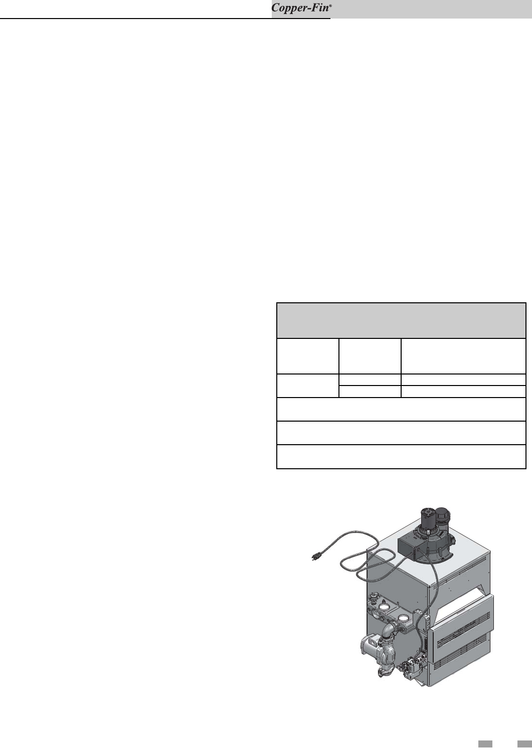
Figure 2-6_CW135 with Fan Assisted Venting
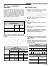
Fan Assisted Venting
A Power Venter kit is available on models 90,000 - 135,000
Btu/hr, water heaters only.