


19
Installation & Service Manual
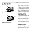
3 Gas connections
Gas Supply
Verify that the appliance is supplied with the type gas
spec i fied on the rating plate. This appliance is orificed for
operation up to 2000 feet altitude. The ap pli ance will be
derated 4% per 1000 feet above 2000 feet el e va tion. Consult
the factory for installations above 2000 feet elevation. Field
conversions for operation at high altitude must be performed
by certified per son nel only. The appliance will be marked to
indicate suitability for high al ti tude operation.
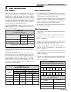
GAS SUPPLY PRESSURE: Measured at the inlet pres sure tap
located upstream of the combination gas valve(s) see
FIG.’s 3-5 and 3-6, page 23.
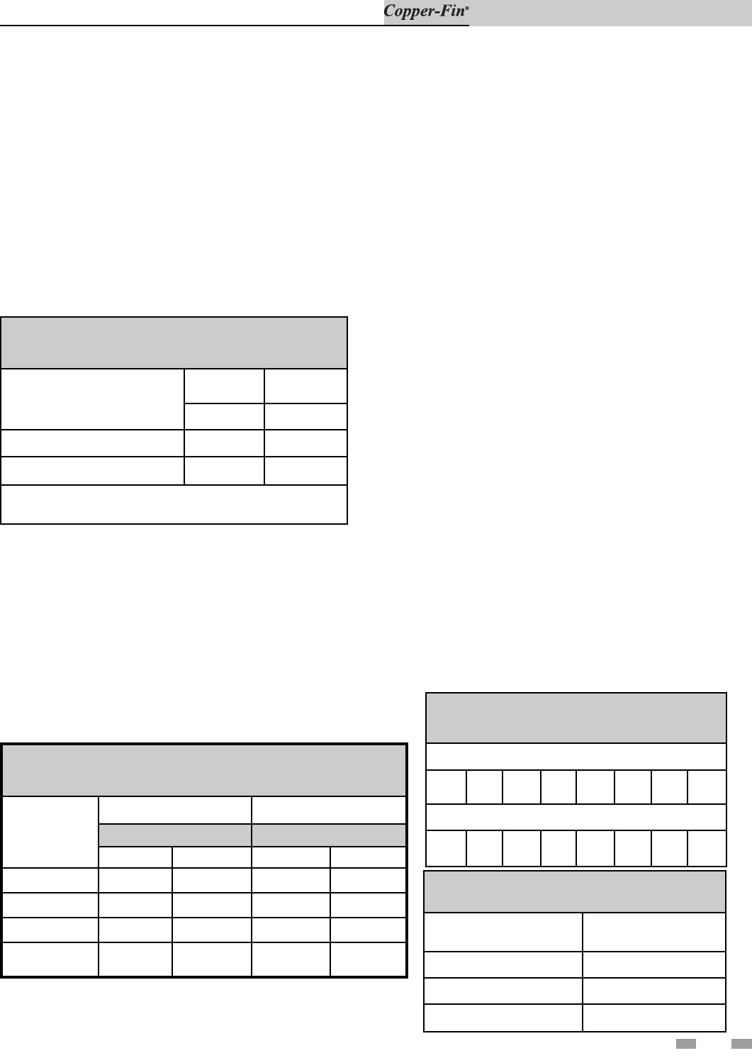
TABLE - 3A
GAS SUPPLY PRESSURE
Max. (Inches Water Column)
Natural Gas LP Gas
14 14
Min. (Inches Water Column) *4.5 11
Min. (Inches Water Column) **5.0 11
*Models 90,000 - 360,000 Btu/hr Only
**Models 399,999 - 500,000 Btu/hr Only
Maximum inlet gas pressure must not exceed the val ue
specified. Minimum value listed is for the purposes of input
adjustment.
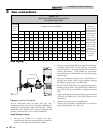
MANIFOLD PRESSURE: Measured at the pres sure tap on
the downstream side of the com bi na tion gas valve(s) (see
FIG.’s 3-5 and 3-6, page 23). The gas regulator settings for
single stage and two stage operation are factory set to supply
proper manifold pressure for normal operation. To check
manifold pressure, see Manifold Ad just ment Procedure. Do
not increase manifold pressure beyond spec i fied pressure
settings shown below in Table 3B.
TABLE - 3B
MANIFOLD PRESSURE
Input Gas
Btu/hr
Single and Two-Stage Two Stage
Full or High Fire Settings Low Fire Settings
Natural Gas LP Gas Natural Gas LP Gas
90,000 - 180,000 3.5" 10" 0.9" 2.5"
199,999 2.9" 7.5" 0.9" 2.5"
215,000 - 399,999 3.5" 10" 0.9" 2.5"
500,000 3.5"
10"
(two valves)
N/A N/A
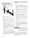
Gas Pressure Test
1. The appliance must be disconnected from the gas supply
piping system during any pressure testing of that system at
a test pressure in excess of 1/2 PSIG (3.5kPa).
2. The appliance must be isolated from the gas supply piping
system by closing a manual shutoff valve during any
pressure testing of the gas supply piping system at test
pressures equal to or less than 1/2 PSIG (3.5kPa).
3. The appliance and its gas connection must be leak-tested
before placing it in operation.
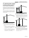
Gas Connection
1. Safe operation of the appliance requires properly sized gas
supply piping.
2. Gas pipe size may be larger than appliance gas connection.
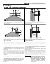
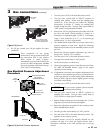
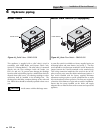
3. Installation of a union is suggested for ease of service, see
FIG. 3-1 on page 20.
4. Install a manual main gas shutoff valve, outside of the
appliance gas connection and before the gas valve or
manifold connection, when local codes require.
5. A trap (drip leg) MUST be provided by the installer in
the inlet of the gas connection to the appliance, see
FIG. 3-1 on page 20.
6. The combination gas valve has an integral vent lim it ing
device and does not require venting to atmosphere,
outside the building.
7. Optional gas controls may require routing of bleeds and
vents to the atmosphere, outside the building when
required by local codes.
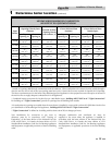
TABLE - 3C
FITTINGS TO EQUIVALENT STRAIGHT PIPE
Diameter Pipe (inches)
3/4 1 1 1/4 1 1/2 2 3 4 5
Equivalent Length of Straight Pipe (feet)
2 2 3 4 5 10 14 20
TABLE - 3D
GAS CONNECTIONS
Btu/hr
INPUT
Pipe Size
90,000 - 135,000 1/2"
180,000 - 315,000 3/4"
360,000 - 500,000 1