


5 Electrical connections (continued)
37
Installation & Service Manual
Installation of a Remote Sensor (Boiler Application)
1. Turn OFF the main electrical power and the main manual
gas shutoff to the appliance.
2. Remove the side access panel from the appliance to gain
access to the thermostat.
3. Locate the sensor in the kit. Determine the location of the
remote sensor and measure the amount of wire needed to
connect the sensor to the thermostat. See Wiring of
Remote Sensors on page 36 for guidelines.
4. Use twisted pair wire, minimum 18 gauge or larger. See
Table 5A, page 33 regarding distance versus wire gauge.
Ensure all wire insulation is trimmed to reveal at least 3/8"
of exposed wire.
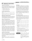
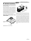
5. Connect the measured wire to the sensor wire using wire
caps (see FIG. 5-5). Install .250 x .032 insulated female
quick connect terminals to the end of the wires. Feed the
wires through the access hole located on the back of the
unit and secure the connectors to the thermostat
connections (Sys/Tank) CN5 and CN6 located in the
upper right-hand of the thermostat.
6. Turn on the electrical power and the main manual gas
shutoff to the appliance.
7. Replace the side access panel.
8. Fire the appliance and resume operation.
Installation of a Tank Sensor (Water Heater
Application)
1. Turn OFF the main electrical power and the main manual
gas shutoff to the appliance.
2. Remove the side access panel from the appliance to gain
access to the wire harness.
3. Locate the two blue wires with a tag notating the remote
thermostat sensor. Feed the blue wires through the access
hole located on the back of the unit.
NOTE: It will be necessary to add additional wire to
reach from the appliance to the remote water source. Use
twisted pair wire, minimum 18 gauge or larger. See Table
5A, page 33 regarding distance versus wire gauge. Ensure
all wire insulation is trimmed to reveal at least 3/8" of
exposed wire.
4. Connect the wires to the sensor wire using wire caps.
5. Turn on the electrical power and the main manual gas
shutoff to the appliance.
6. Replace the side access panel.
7. Fire the appliance and resume operation.
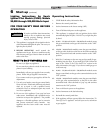
ACCESS HOLE
CONNECT THE MEASURED
WIRE TO THE SENSOR WIRE
Figure 5-5_Installation of Remote Sensors
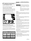
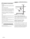
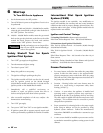
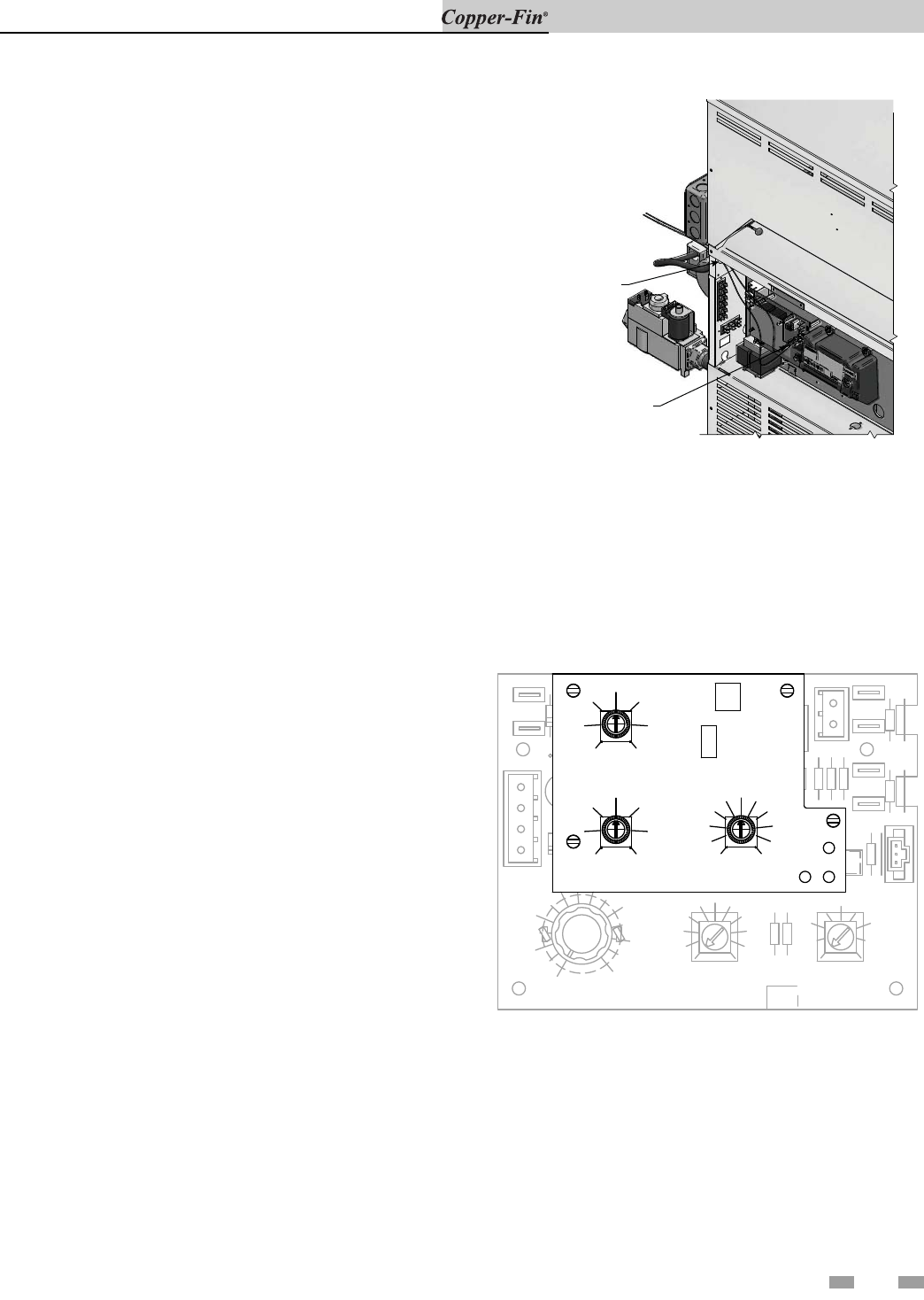
Outdoor Air Reset Option
For boilers ordered with the Outdoor Air Reset option,
there is an additional control (FIG. 5-6). There are three
setting knobs for Shutdown, Outdoor Air Max., and Ratio.
There is also a switch to turn the outdoor air shutdown
feature On or Off. An O.A. Sensor is also included.
R4
R4
R6
R6
R8
R8
R16
R16
R15
R15
C7
C7
C9
C9
C10
C10
VR2
VR2
VR3
VR3
OJ1
OJ1
OJ2
OJ2
D4
D4
J4
J4
CN1
CN1
CN2
CN2
CN9
CN9
CN7
CN7
CN8
CN8
CN3
CN3
CN4
CN4
CN5
CN5
CN6
CN6
W1
W1
TST2314
TST2314
20
20
15
15
10
10
5
5
(F-)0
(F-)0
15
15
14
14
13
13
12
12
11
11
10
9
9
8
8
7
7
6
6
5
5
OFF
OFF
120
120
240
240
220
220
200
200
160
160
140
140
SETPOINT
SETPOINT
DIFFERENTIAL
DIFFERENTIAL
HIGH-FIRE
HIGH-FIRE
OFFSET
OFFSET
(c)2002 L.C.
(c)2002 L.C.
SHUTDOWN
45
50
45
1.3
O.A. MAX.
70
40
VR1
65
RATIO
VR2
0.6
0.5
0.7
1.4
1.5
W1 W2
W3
60
50
7040
55
60
VR3
65
DISABLE
O.A. SHUTDOWN
1.0
0.9
0.8
1.2
1.1
O.A. SENSOR
ENABLE
ON
SW1
55
CN1
Figure 5-6_Optional Outdoor Air Reset Control