


3 Gas connections (continued)
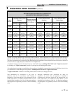
21
Installation & Service Manual
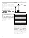
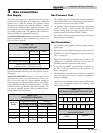
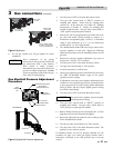
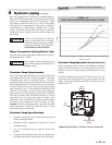
APPLY WRENCH
TO FLANGE ONLY
WHEN FLANGE
IS USED
APPLY WRENCH FROM
BOTTOM OF GAS CONTROL
TO EITHER SHADED AREA
WHEN FLANGE
IS NOT USED
Figure 3-2_Wrench
8. For L.P. gas, consult your L.P. gas supplier for expert
installation.
IMPORTANT
Upon completion of any piping
con nec tions to the gas system, leak test all
gas con nec tions with a soap solution
while system is un der pressure.
Immediately repair any leaks found in the
gas train or related components. Do Not
op er ate an appliance with a leak in the gas
train, valves or related piping.
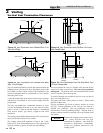
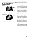
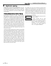
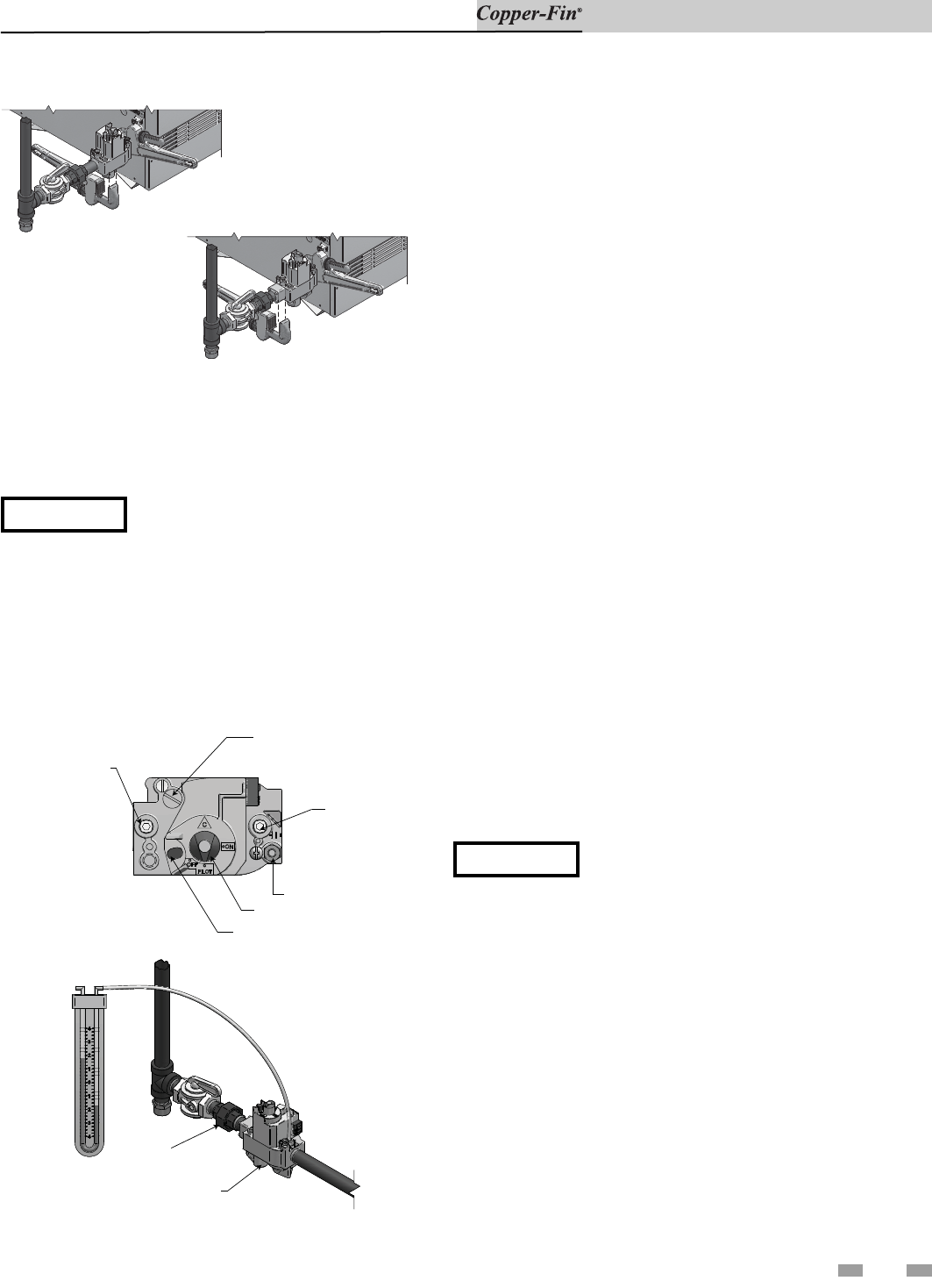
Gas Manifold Pressure Adjustment
Procedure
PRESSURE REGULATOR
ADJUSTMENT
(UNDER SCREW CAP)
OUTLET
PRESSURE TAP
PILOT OUTLET
GAS CONTROL KNOB
RED RESET BUTTON
INLET
PRESSURE
TAP
UNION
GAS VALVE
MANOMETER
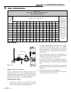
Figure 3-3_Manifold Pressure Adjustment
1. Turn the power “OFF” at the main dis con nect switch.
2. Turn gas valve control knob to “PILOT” po si tion on
standing pilot models. Ensure that the stand ing pilot
remains on. If the pilot goes out, follow the “Lighting
Instructions” in Section 6 - Startup for standing pi lot
models to light the pilot. Turn gas valve control knob to
“OFF” po si tion on spark ignition models.
3. Remove the 1/8" hex plug located on the out let side of the
gas valve and install a fitting suitable to connect to a
manometer or magnahelic gauge. See FIG. 3-3. Minimum
range of scale should be up to 5" w.c. for Natural gas
mod els and 10" w.c. for L.P. gas models.
4. The 500,000 Btu/hr model will have two gas valves with a
pressure regulator on each valve. Repeat the following
adjustment pro ce dure to set the manifold pressure on each
gas valve.
5. Remove the pressure regulator adjustment cap screw on
the gas valve. See FIG. 3-3 for location.
6. Turn the power “ON” at the main dis con nect switch.
7. Turn gas valve control knob to “ON” po si tion.
8. Set the thermostat(s) to call for heat.
9. Observe gas regulator pressure when all burn ers are firing.
See Table 3B, Manifold Pressure (page 19) for proper
regulator pressure settings.
10. If adjustment is necessary, turn regulator ad just ment screw
clockwise to raise regulator gas pres sure, counterclockwise
to lower gas pres sure, to proper setting. N
OTE: Adjustment
fitting is plas tic and may require slightly greater turning
force than a metal fitting.
11. Turn the power “OFF” at the main dis con nect switch.
NOTICE
Do not increase regulator pres sure beyond
specified pressure setting.
12. Turn gas valve control knob to “PILOT” po si tion on
standing pilot models. Turn gas valve control knob to
“OFF” position on spark ignition models.
13. Remove fitting from the gas valve and re place the 1/8" hex
plug that was previously removed and tighten.
14. Repeat the adjustment procedure for the sec ond gas valve
on the 500,000 Btu/hr model.
15. Turn the gas valve control knob(s) to “ON” position.
16. Turn the power “ON” at the main dis con nect switch. The
appliance is now ready to op er ate.
If manifold pressure can not be properly adjusted, use the
procedure on page 22 to check gas supply pressure with a
manometer connected to the inlet pressure tap on the gas
control.