


8 Maintenance (continued)
59
Installation & Service Manual
p. Check “V” baffles on top of the heat ex chang er.
Remove and clean if necessary.
q. Remove soot from the heat exchanger with a stiff
bristle brush. Soot may also be re moved from the
heat exchanger by washing thoroughly with
detergent and water. Remove the heat exchanger
before using water for cleaning. Rinse thoroughly
and dry before re-installing. Use a vacuum
to remove loose soot from surfaces and in ner
chamber.
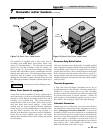
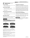
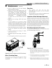
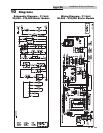
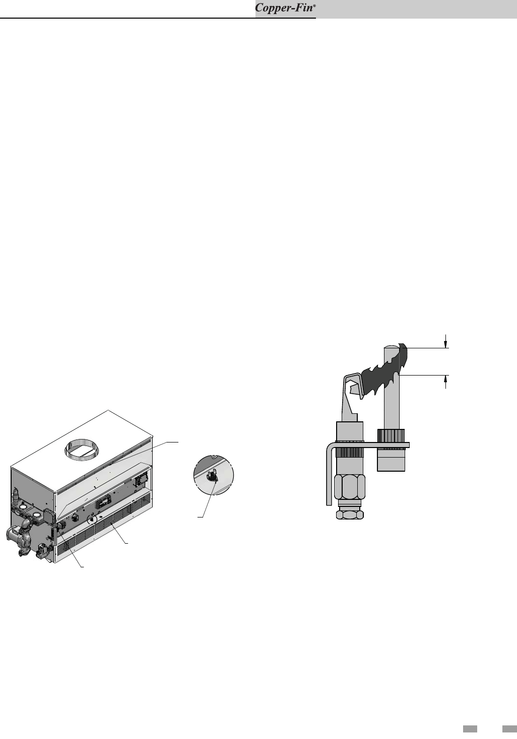
r. Remove the heat exchanger (HEX) filler bracket
(FIG. 8-2).
s. The heat exchanger can be removed by sliding
towards the front of the appliance. Once the heat
exchanger is removed from the ap pli ance, a garden
hose can be used to wash the tubes to ensure that all
soot is removed from the heat exchanger surfaces.
t. Ensure that all burner ports are cleaned to remove
any soot. See Inspection and Cleaning Procedure,
page 58.
u. Carefully re-install the heat exchanger, “V” baffles,
jacket panels, and wires.
v. Reassemble all gas and water piping. Test for gas
leaks.
w. Cycle the appliance and check for prop er operation.
DETAIL
HEX FILLER BRACKET
FLAME
ROLL-OUT SWITCH /
INTERLOCK SWITCH
UPPER FRONT
JACKET PANEL
LOWER FRONT
JACKET PANEL
Figure 8-2_Outer Air Deflector and HEX Filler Bracket
Water Circulating Pump
Inspect pump ev ery 6 months and oil if required. Use SAE 30
non-detergent oil or lubricant specified by pump
man u fac tur er.
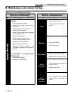
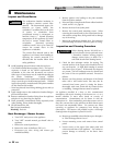
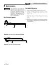
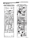
Pilot Flame Adjustment Procedure
The pi lot flame should envelop 3/8" to 1/2" (10 to 13mm) of the
tip of the thermocouple (see FIG. 8-3).
1/2"
Figure 8-3_Pilot Flame on Thermocouple
a. Remove pilot adjustment cover screw on the gas valve.
See the Gas Valve illustrations in the Lighting
Instructions section (page 41) for the lo ca tion of the
cover screw.
b. Turn the inner adjustment screw clock wise to decrease
or counterclockwise to increase pilot flame.
c. Replace the pilot adjustment cover screw on the valve.
Tighten firmly after adjustment to prevent gas leakage.
Clear Area
1. Keep appliance area clear and free from
com bus ti ble materials, gasoline and other flammable
vapors and liquids.
2. Check frequently to be sure the flow of com bus tion and
ventilation air to the boiler is not obstructed.
Inspection of Heat Exchanger Waterways
Appliances operated in hard water areas should have periodic
inspections of the tubes to be sure that no sediment or scale
accumulates on the heat transfer sur fac es. Inspection plugs are
located at both ends of the heat exchanger. In spec tion plugs
should be removed and tubes inspected at the end of the first 45
days of operation and again at the end of 90 days of operation.
If no scale accumulation is ob served, inspections can be made at
the end of each six months of op er a tion.