


7 Domestic water heaters (continued)
51
Installation & Service Manual
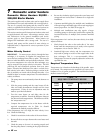
Minimum Pump Performance
Based on heating potable water with a hardness of 8 to 25
grains per gallon and total dissolved solids not exceeding
350 ppm. See “Water Chemistry”, page 47.
BTU/hr INPUT
GPM Ft. Hd.
90,000 - 500,000 30 8
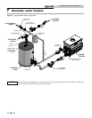
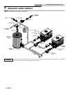
Remote Sensor Installation
Water heaters are provided with an extra temperature sensor
that MUST BE field installed. The sensor is shipped loose in
the I & O packet. This remote mounted sensor will be the
primary temperature sensor which will inform the appliance’s
built-in thermostat control. For domestic water heating, the
sensor MUST BE installed into a bulbwell on the storage tank.
This is required to maintain the desired temperature in the
tank and reduce cycling of the heater.
The sensor must also be connected to two blue wires provided
in the upper left-hand corner of the control panel. It will be
necessary to add additional wire to reach from the appliance
to the remote water source. Use twisted pair wire, minimum
18 gauge or larger. See Table 5A, page 33 regarding distance
versus wire gauge.
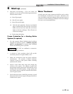
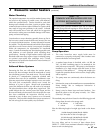
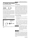
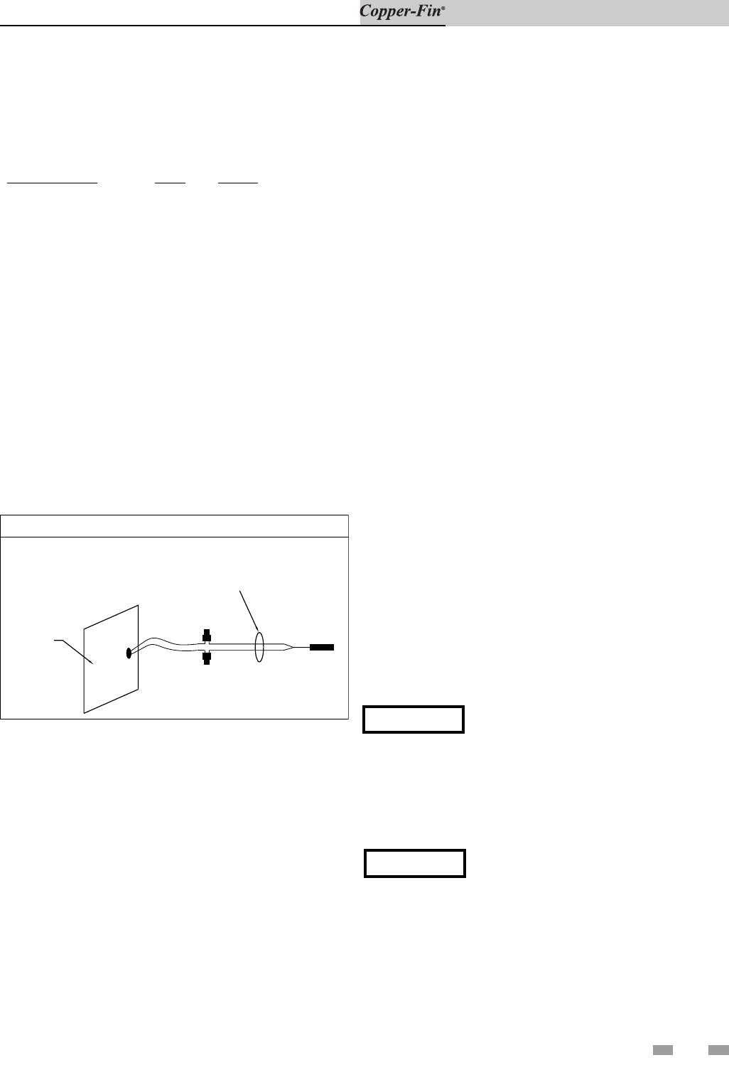
INSTRUCTIONS
EXTERNAL SENSOR FOR TANK, SYSTEM OR PUMP DELAY
REMOTE SENSOR CONNECTOR IS
LOCATED ON SIDE OF UNIT.
NOTE: COLOR OF WIRES AND
LEAD STYLES MAY VARY
WITH SENSOR PROVIDED.
CONNECTIONS ARE POLARITY
INSENSITIVE.
SIDE PANEL
Figure 7-4_External Sensor for Tank, System or Pump
Delay
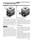
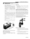
Heat Exchanger
This is a highly sophisticated heat exchanger, de signed to carry
water in such a way that it gen er ates a scour ing action which
keeps all interior sur fac es free from build-up of impurities. The
straight-line, two pass de sign of the tubes sends water into the
headers at a properly rated velocity. The configuration of the
head ers, in turn, creates a high degree of turbulence which is
sufficient to keep all contaminants in suspension. This
“scouring action” provides greater cost savings for owners.
Tubes are always able to transfer heat at peak ef fi cien cy. Every
surface within this water con tain ing section is of a nonferrous
material, providing clear, clean, rust-free hot water. Straight
copper tubes-finned on the outside for maximum heat transfer
glass lined cast iron one piece cored head ers make up an entirely
rustproof unit. On all mod els, header inspection plugs can be
removed for field in spec tion and cleaning of copper tubes. The
entire heat exchanger may be easily removed from the unit.
Thermostat Settings
1. The thermostat is adjusted to a low test set ting when
shipped from the factory.
2. Set the thermostat to a maximum water temperature of
125°F which will satisfy hot water demands and prevent
risk of scald injury.
Households with small children or invalids may require
120°F or lower temperature setting to re duce risk of scald
in ju ry. Some states may require a lower temperature
setting. Check with your gas supplier for local
re quire ments governing the tem per a ture setting.
Re mem ber, no water heating sys tem will provide exact
tem per a ture at all times. Allow a few days of operation at
this setting to de ter mine the correct temperature set ting
consistent with your needs.
NOTICE
(1) This water heater, when set at the
low er temperature setting, is not capable
of producing hot water of sufficient
temperature for sanitizing pur pos es. (2)
Higher stored water temperature
in creas es the ability of the water heater to
supply desired quantities of hot water,
however remember:
ƽ CAUTION
Hotter water increases the risk of scald
injury.
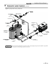
Incorrect piping of the cold water supply to the sys tem may
result in excessive low temperature op er a tion causing
condensate formation on the heat ex chang er and operational
problems. The cold water supply piping must be installed in the
dis charge piping from the heater to the storage tank. This allows
the cold water to be tempered in the storage tank before entering
the heater. See typ i cal installation drawings provided in this
manual. Higher wa ter temperatures reduce condensate
formation.