


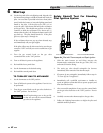
46
7 Domestic water heaters
Installation & Service Manual
Domestic Water Heaters 90,000 -
500,000 Btu/hr Models
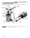
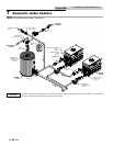
This section applies only to those units used to sup ply direct
fired domestic hot water and installed with a storage tank(s).
The use of a properly sized pump and the control of water
velocity, as ex plained in the Water Velocity Control section, are
important for correct operation of your hot water heater.
This section contains specific instructions for those units used
to supply domestic hot water. All warn ings, cau tions, notes
and instructions in the gen er al installation and service
sections apply to these instructions. Water heat ers are
designed for installation with a storage tank. The use of a
properly sized pump and the control of water velocity, as
ex plained below, is important for correct operation of your
water heater.
Water Velocity Control
IMPORTANT - To ensure proper velocity through the heat
exchanger, it is necessary to regulate the tem per a ture rise
across the heat exchanger from inlet to outlet. This must be
done on initial in stal la tion and periodically rechecked. With
the correct temperature rise across the heat exchanger, you
may be assured of the proper velocity in the tubes. This will
yield long life and economical operation from your water
heater. Excessive lime build-up in the tube is a result of too
little velocity in the tubes. Excessive pit ting or erosion in the
tube is caused by too much ve loc i ty through the tubes. Care
should be taken to measure tem per a ture rise and maintain a
velocity as follows:
1. The pump must run continuously when the burners are
firing.
2. With the pump running and the water heat er off, the
inlet and outlet ther mom e ters should read the same
temperatures. If they do not, an adjustment must be
made to your final calculation.
3. Turn the water heater on and allow time for the
temperature to stabilize. Record the difference between
the inlet and outlet temperatures. This difference will be
the “tem per a ture rise.”
4. Compare the temperature rise on the heater with the
required temperature rise in Table 7A. Should
adjustment be needed, proceed as fol lows:
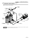
If the temperature rise is too high, the water ve loc i ty is too
low. Check the following:
1. Check for restrictions in the outlet of the wa ter heater.
2. Be sure all valves are open between the water heater and
the tank.
3. Check the pump to be sure it is running prop er ly and
that the pump motor is running in the proper direction.
4. Be sure the circulation pipes between the wa ter heater and
storage tank are not less than 2" diameter for a single unit
installation.
5. Common manifold piping for multiple unit in stal la tions
will require larger minimum pipe siz es to tank tappings to
ensure proper flow. See Table 7B on page 47.
6. Multiple unit installations may also require a larger
circulating pump to achieve the specified flow against the
increased head loss of multiple unit com mon manifold
piping.
If the temperature rise is too low, the water ve loc i ty is too high.
Adjust as follows:
1. Slowly throttle the valve on the outlet side of the water
heater until the temperature rise is steady at the required
tem per a ture rise as noted in Table 7A.
2. Sustained high water velocity and low tem per a ture rise
may result in pitting or erosion of the copper tubes in the
heat exchanger. This is a non-warrantable failure.
Temperature rise must be properly adjusted to achieve the
specified flow rate.
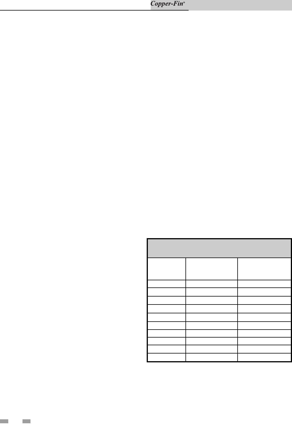
Required Temperature Rise
Temperature rise is based on the hardness of the potable water
to be heated. The temperature rise specified is for water with a
hardness of 5 to 25 grains per gallon. The total dissolved solids
shall not exceed 350 ppm.
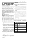
TABLE - 7A
REQUIRED TEMPERATURE RISE
Btu/hr
INPUT
Flow Rate
GPM
Temperature Rise °F
90,000 30 5
135,000 30 7
180,000 30 10
199,999 30 11
225,000 30 12
270,000 30 15
315,000 30 17
360,000 30 20
399,999 30 22
500,000 30 28