


3 Gas connections (continued)
23
Installation & Service Manual
Combination Gas Valves
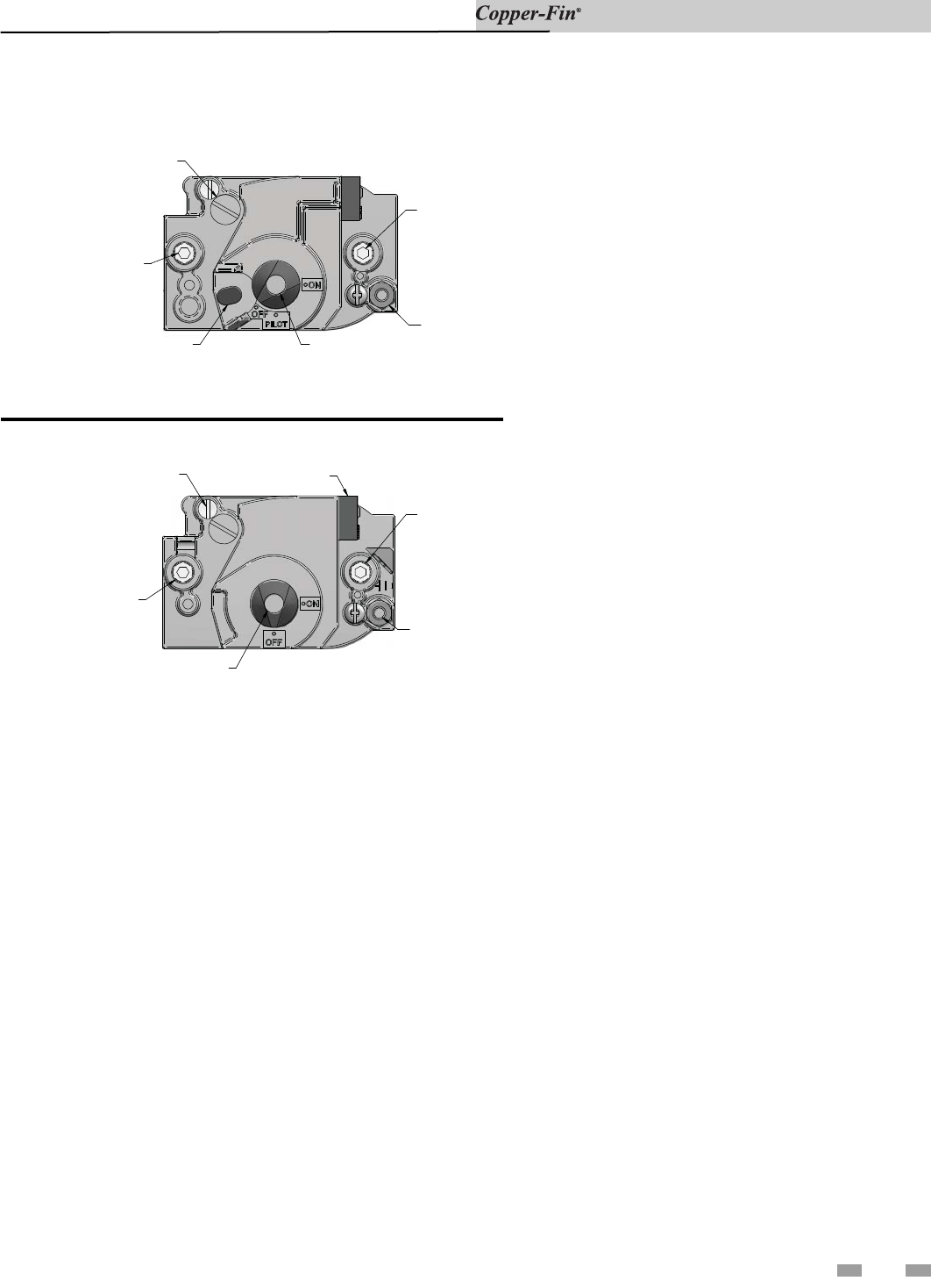
WIRING TERMINALS
PRESSURE REGULATOR
A
DJUSTMENT (UNDER CAP SCREW)
INLET PRESSURE TAP
GAS CONTROL KNOB
PILOT OUTLET
OUTLET
PRESSURE TAP
PRESSURE REGULATOR
A
DJUSTMENT (UNDER CAP SCREW)
INLET PRESSURE TAP
RED RESET BUTTON
PILOT OUTLET
OUTLET
PRESSURE TAP
GAS CONTROL KNOB
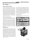
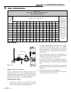
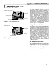
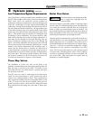
Figure 3-5_F1 Gas Valve, standing pilot
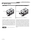
Figure 3-6_F9 Gas Valve, spark ignition
Each unit has a combination gas valve(s) to control the
gas supply to the burners. The 500,000 Btu/hr model has
two combination gas valves to supply gas to the burners.
The com bi na tion valve con sists of a gas regulator and
two valve seats to meet the requirements for redundant
gas valves. The valve has a gas control knob that must
remain in the open po si tion at all times when the
appliance is in service. Each gas valve has pres sure taps
located on the inlet and outlet sides. Manifold pressure
is adjusted using the regulator located on the valve. The
manifold pres sure is pre set at the factory and adjustment
is not usu al ly re quired. If the manifold pressure is to be
ad just ed, follow the “Gas Manifold Pressure Ad just ment
Pro ce dure”, page 21 for proper adjustment.
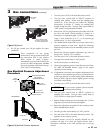
Venting of Combination Gas Valves
The combination gas valve regulator used on all mod els
is equipped with an integral vent limiting orifice. The
vent limiter ensures that the volume of gas emitted from
the valve does not exceed the maximum safe leak age rate
allowed by agency re quire ments. Com bi na tion gas
valve/regulators equipped with integral vent limiters are
not re quired to have vent or relief lines piped to the
outdoors. A dust cap is provided at the vent termination
point on the valve to prevent block age of the vent limiter
by foreign material. The com bi na tion gas valve
regulator with an integral vent limiter complies with the
safety code requirements of CSD-1, CF-190(a) as
shipped from the manufacturer with out the in stal la tion
of additional vent lines.
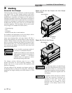
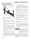
Two Stage Burner Control System
The 315,000 through 399,999 Btu/hr boiler models (M9)
will be equipped with a two stage gas valve to control
high/low burner op er a tion. The 500,000 Btu/hr boiler
mod el achieves two stage burner firing by staging the
operation of the two combination gas valves.