


NOTE: DIAGRAMS & ILLUSTRATIONS ARE NOT TO SCALE.
9
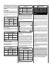
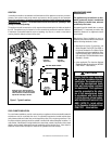
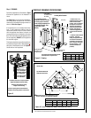
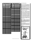
Figure 9 - Framing
FIREPLACE FRAMING SPECIFICATIONS
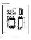
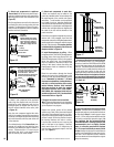
Figure 10 - Corner Framing with Square Termination (SV4.5HT-2)
Framing Dimensions - All Models
A B C D
in. 22-1/8 40-1/4 15-3/4 44-1/8
mm 562 1022 400 1121
Inches
(millimeters)
C
Back wall of chase/enclosure
(including any finishing materials)
E
D
A
B
7 (178)
�
Corner Framing Dimensions - All Models
A B C D E
in. 22-1/8 41-5/8 29-1/2 10 20-7/8
mm 562 1057 749 254 530
Framing With Platform
Inches (mm)
The platform should extend the full width
and depth of the fireplace base.
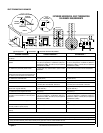
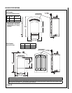
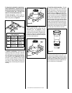
Top Vent With Horizontal
Termination In A Corner
(MJ) Need review of updated dimen-
sions in tables below (4-17-08)
* D shown here is not
dimensioned to the vertical
center of the horizontal
framing. This is to allow for
the required 4" clearance
above the vent and the 1"
required clearance below
the vent. This does not
include the suggested 1/4"
rise per foot for horizontal
runs.
** With the facade installed
(required - sold sepa-
rately), the appliance base
will need to be elevated a
minimum of 3/4" above the
floor to allow for the proper
fit of the facade (i.e. use
3/4" board minimum as
platform).
uWhen installing in a corner configuration, one of
the rear stand-offs will need to be removed.
Step 1. FRAMING
Frame these appliances as illustrated in Figure
9, unless the appliance is to be installed in a
corner.
See
Figure 10 for corner framing installations.
All framing details must allow for a minimum
clearance to combustible framing members as
shown in
Table 6 on Page 6.
If the appliance is to be elevated above floor
level, a solid continuous platform must be
constructed. Headers may be in direct contact
with the appliance top spacers but must not
be supported by them or notched to fit around
them. All construction above the appliance must
be self supporting,
DO NOT use the appliance
for structural support.
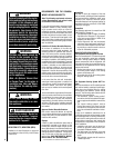
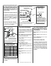
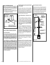
The fireplace should be secured to the side fram
-
ing members using the unit's nailing flanges
on
each side of the fireplace front. See
Figure 8.
Use 8d nails or their equivalent.
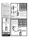
Figure 8
Left Side Front Corner of Fireplace Shown
(Right Side Requirements the Same)
Unit Being Secured By Its Nailing
Flanges To The Framing
Frame the opening to the exact dimensions
specified in the framing details in this manual.
Use Top Flange For
5/8” Thick Drywall
Use Center Flange For
1/2” Thick Drywall
Use Bottom Flange
For Flush Mount
D*
B
VENT FRAMING -
TOP VENT WITH ONE
90° ELBOW
Framing should be
constructed of 2x4
or larger lumber
2 x 4 Header must be
installed, vertical as shown
to allow proper clearance
from venting components to
combustible header. See
Figure 50 for more
details.
A
C
Platform
**
Inches (mm)
8
(203)
5-1/8
13-1/8
(333)
10-1/2
(267)
(130)
3/4” Minimum from
Finished Floor