


NOTE: DIAGRAMS & ILLUSTRATIONS ARE NOT TO SCALE.
23
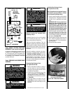
WARNING
Do not operate appliance with
the glass front removed, cracked
or broken.
WARNING
Do not attempt to substitute
the materials used on this
door. Do not attempt to replace
broken, cracked or chipped glass
separately. The glass door of this
appliance must only be replaced
as a complete unit as provided by
the manufacturer.
WARNING
Do not attempt to touch the front
enclosure glass with your hands
while the fireplace is in use.
Remove the glass door assembly before
proceding to Step 7.
A required firebox liner kit must be installed
prior to installing the glass door. Install the
liner per instructions provided in kit.
These are direct-vent appliances. They are
designed to operate only when the front glass
enclosure panel is installed. Generally the front
glass enclosure panel should not be removed
except to gain access to the components within
the firebox
.
During this appliance checkout and adjust
-
ment period, a potential safety hazard exists
- EXERCISE EXTREME CAUTION to prevent
the occurrence of any burn injuries from the
exposed flames or hot surfaces. Also note,
that while the front glass enclosure panel is
removed, the flame appearance will appear to
be smaller than normal.
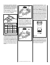
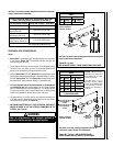
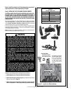
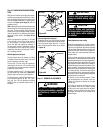
Removing Glass Enclosure Panel
(see Figure 38a and 38b)
1. Remove the facade assembly by lifting it
up and toward you (see the installation
instruction sheet provided with the facade
for additional information).
2. Locate the two (2) latches at the top of the
control compartment (see
Figure 38a). To
disengage the two latches, pull the spring-
loaded latches forward then down as shown
in
Figure 38a.
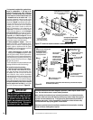
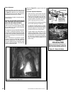
3. Swing the bottom of the door out (see
Figure 38b) and raise it slightly to lift the
top flange of the door frame away from the
appliance.
WARNING
Be careful not to abuse the glass
enclosure assembly by striking
or slamming it. Handle this
glass with extreme care! Glass
is susceptible to damage – Do
not scratch or handle roughly
while reinstalling the glass door
frame.
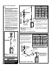
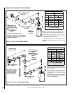
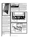
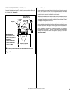
BLOWER CONTROL CIRCUIT WIRING
120V, 60HZ, 1PH
Factory Wired
Ground
Field Wired
Junction Box
Tab Intact
Tab
Broken
Plug blower
into this
receptacle
n
e
e
r
G
-
dn
u
o
r
G
* Wall-mounted
ON/ OFF Blower
Switch or Variable
Speed Control Switch.
Blower
e
ti
h
W
-
lar
t
u
e
N
120 VAC - Black
Green
Ground
Screw
White
Green
Neutral
Side of
Receptacle
Hot
Side of
Receptacle
Red
Black
Figure 37 - J-BOX WIRING
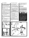
Step 5. WIRING - OPTIONAL FORCED AIR
BLOWER KIT (See Figure 35 on Page 22)
An electrical outlet box is provided for the
installation of the
LBLK-100 forced air blower
kit. Electrical power must be provided to this
box to operate these blowers. Install the blower
kit according to the installation instructions
provided with the kit.
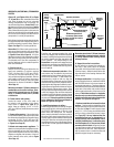
Step 6. REMOVING GLASS DOOR FRAME
ASSEMBLY
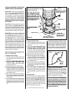
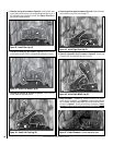
Installing Glass Enclosure Panels
(see Figure 38a and 38b)
Note: This appliance is not approved for opera-
tion without a log set (provided) or a firebox
liner kit installed (sold separately).
1. Visually inspect the gasket on the backside
of the glass panel. The gasket surface must
be clean, free of irregularities and seated
firmly.
IMPORTANT NOTE: Be very careful not to
damage the refractory firebox liner when
installing the door. Take care when seat-
ing the top door gasket so that it is not
obstructed by the refractory panel. If the
door feels restricted when latching, the top
door gasket may not be properly seated.
2. Position the glass enclosure panel in front
of the firebox opening at a 45 degree angle
and engage the top flange over the lip at the
top of the firebox opening (read important
note above).
See Figure 38b.
3. Swing the glass enclosure panel down and
back. Ensure the gasket seats evenly as
the panel draws shut. Close the latches to
secure the panel.
4. Reinstall the facade assembly.
Figure 38a - Glass Door Latches
Spring-Loaded Latches
Pull forward then down to release
Pull Latches
Forward