


8
NOTE: DIAGRAMS & ILLUSTRATIONS ARE NOT TO SCALE.
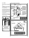
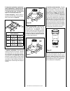
Figure 7
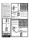
See Figure 28 on Page 18 for the recess allowances, into
exterior walls, of the square horizontal terminations.
TYPICAL INSTALLATION SEQUENCE
The typical sequence of installation follows,
however, each installation is unique resulting
in variations to those described. See the page
numbers references in the following steps for
detailed procedures.
Step 1. (Page 9) Construct the appliance fram-
ing. Position the appliance within the framing
and secure with nailing brackets.
Step 2. (Page 12) Route gas supply line to
appliance location.
Step 3.
(Page 12) Install the vent system and
exterior termination.
Step 4. (Page 22) Field Wiring
a. Millivolt Appliances –
The operating control
switch is factory installed.
b. Electronic Appliances – Connect 120 Vac
electrical power to the appliance recep
-
tacle.
Step 5. (Page 23) Install blower kit (optional
equipment).
Step 6. (Page 23) Remove glass door frame
assembly.
Step 7. (Page 24) Make connection to gas
supply.
Step 8. BEFORE PROCEEDING TO STEP 9,
INSTALL A FIREBOX LINER KIT PER INSTRUC
-
TIONS PROVIDED IN THE KIT (REQUIRED
- SOLD SEPARATELY).
Step 9. (Page 25) Install the logs and glowing
embers.
Step 10. (Page 27) Checkout appliance op-
eration.
Step 11. (Page 27) Adjust burner to ensure
proper flame appearance.
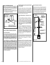
DETAILED INSTALLATION STEPS
The appliance is shipped with all gas controls
and components installed and pre-wired. Re
-
move the shipping carton, exposing the front
glass door. Pull out the two spring loaded
latches securing the glass door (located under
the firebox floor). Remove the door by tilt
-
ing it outward at the bottom and lifting it up
and off. Set the door aside protecting it from
inadvertent damage.
See Figure 38a and 38b
on Page 23.
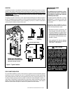
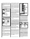
Figure 6
These instructions should be used as a guide-
line and do not supersede local codes in any
way. Install vent according to local codes,
these instructions, the current National Fuel
Gas Code (ANSI-Z223.1) in the USA or the
current standards of CAN/CGA-B149.1 and
-B149.2 in Canada.
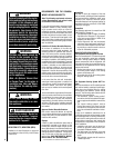
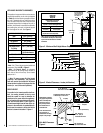
Horizontal Vent Termination Clearances
The horizontal vent termination must have
a minimum of 3" (76 mm) clearance to any
overhead combustible projection of 2-1/2" (64
mm) or less. See
Figure 7. For projections
exceeding 2-1/2" (64 mm), see
Figure 5. For
additional vent location restrictions refer to
Figure 5 on Page 7.
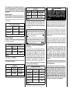
Vertical Vent Termination Clearances
Terminate single vent caps relative to building
components according to
Figure 6.
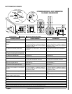
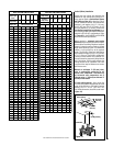
Termination Heights For Vents
Above Flat Or Sloped Roofs
Ref. NFPA 54 / ANSI Z223.1, 7.6
Roof Pitch * Feet * Meters
Flat to 6/12
1.0 0.3
6/12 to 7/12
1.25 0.38
7/12 to 8/12
1.5 0.46
8/12 to 9/12
2.0 0.61
9/12 to 10/12
2.5 0.76
10/12 to 11/12
3.25 0.99
11/12 to 12/12
4.0 1.22
The vent / air intake termination clearances
above the high side of an angled roof is as
shown in the following chart:
12
X
Roof Pitch is X/12
2 FT
MIN.
2 FT MIN.
Lowest
Discharge
Opening
H*
*H = MINIMUM HEIGHT FROM ROOF TO
LOWEST DISCHARGE OPENING OF VENT
TERMINATION HEIGHTS FOR VENTS ABOVE
FLAT OR SLOPED ROOFS
Horizontal Overhang
Vertical
Wall
Vent
Termination
Storm Collar
Concentric
Vent Pipe
Flashing
1 inch (25.4 mm) Minimum
Clearance to Combustibles
Terminate multiple vent terminations accord-
ing to the installation codes listed at the top
of
this Page.
3"
(76 mm)
12"
(305 mm)
Combustible Projection greater
Horizontal Vent Termination Clearances
Combustible Projection
2-1/2”(64mm) or less in length
18"
(457 mm)
Ventilated
Soffit
Unventilated
Soffit
than 2-1/2”(64mm) in length
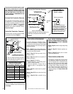
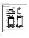
Side Elevation View
SV4.5HT-2 Termination Kit
SV4.5HT-2 Termination Kit
Side Exterior
Wall
MINIMUM ALLOWABLE
SIDE WALL CLEARANCE
All horizontal terminations may be
located as close as 6” (152mm) to any
(non-combustible and combustible)
exterior sidewall. This distance may be
decreased to 2” (51mm) for non-
combustible exterior sidewalls only, if
the SV4.5HT-2 termination is used.