


24
NOTE: DIAGRAMS & ILLUSTRATIONS ARE NOT TO SCALE.
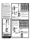
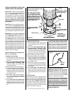
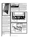
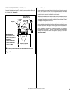
Gas Valve
Burner
ON/OFF Switch
Push Button
Piezo Igniter
Figure 39 - Control Compartment
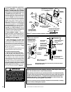
Glass Door
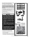
Gas Shut-
Off Valve
Gas Flex-
Line
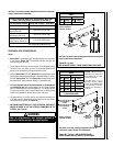
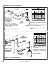
Step 7. CONNECTING GAS LINE
Make gas line connections. Codes require a
shut-off valve mounted in the supply line.
Figure
40 illustrates two methods for connecting the
gas supply. The flex-line method is acceptable
in the U.S., however, Canadian requirements
vary depending on locality. Installation must
be in compliance with local codes.
These appliances are equipped with a gas flex
line for use (where permitted) in connecting the
unit to the gas line. A gas flex line is provided
to aid in attaching the direct vent appliance to
the gas supply. The gas flex line can only be
used where local codes permit. See
Figure 40
for flex line description. The flex line is rated for
both natural and propane gas. A manual shut off
valve is also provided with the flex line.
If required, access the valve (see
Figure 39 ) by
opening the lower control panel (see instruction
sheet provided with the facade kit for additional
information about the control panel).
The millivolt and electronic control valve has a
3/8" (10 mm) NPT thread inlet port.
Bring the shutoff valve on the end of the flex line
over to the hard pipe and tighten with wrenches
from above through the firebox opening.
Secure all joints tightly using appropriate
tools and sealing compounds (ensure propane
resistant compounds are used in propane
applications).
Optional: Seal around the gas line to prevent
cold air leakage.
WARNING
Never use an open flame to
check for leaks.
Turn on gas supply and test for gas leaks using a
gas leak test solution (also referred to as bubble
leak solution).
Note: Using a soapy water solution
(50% dish soap, 50% water) is an effective leak
test solution but it is not recommended, because
the soap residue that is left on the pipes/fittings
can result in corrosion over time.
Gas
Valve
3/8" NPT x
Flare Fitting
3/8" Flex Tubing
3/8" Nipple
3/8" Union
3/8" Close Nipple
3/8" Shut-off Valve
1/2" x 3/8"
Reducer
Gas
Stub
1/2" x 3/8" Flare
Shut-off Valve
Gas Solid Line Connector
Gas Flex Line Connector
*Sediment
Trap
3"
Min
Note: The gas supply line
must be installed in accor-
dance with building codes
by a qualified installer
approved and/or licensed
as required by the locality.
In the Commonwealth of
Massachusetts, installation
must be performed by a
licensed plumber or gas
fitter.
*A Sediment Trap is recom-
mended to prevent moisture
and debris in gas line from
damaging the valve.
Figure 40
GAS CONNECTION
A. Light the appliance (refer to the lighting instruc
-
tions label in control compartment or care and
operation manual).
B. Brush all joints and connections with the gas
leak test solution to check for leaks. If bubbles
are formed, or gas odor is detected, turn the
gas control knob (off/pilot/on) to the “OFF”
position. Either tighten or refasten the leaking
connection, then retest as described above.
C. When the gas lines are tested and leak free be
sure to rinse off the leak testing solution,
D. Turn on burner then observe the individual
tongues of flame on the burner. Make sure
all ports are open and producing flame evenly
across the burner. If any ports are blocked, or
partially blocked, clean out the ports.
TEST ALL CONNECTIONS FOR GAS LEAKS
(FACTORY AND FIELD):
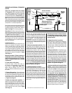
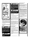
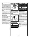
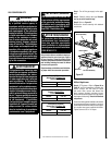
Figure 38b - Glass Door Removal
Door
Assembly