


NOTE: DIAGRAMS & ILLUSTRATIONS ARE NOT TO SCALE.
27
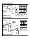
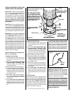
Step 11. BURNER ADJUSTMENTS
WARNING
Air shutter adjustment should
only be performed by a qualified
professional service techni-
cian.
IMPORTANT
Ensure front glass panel are in
place and sealed during adjust-
ment.
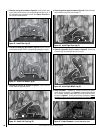
Flame Appearance and sooting
Proper flame appearance is a matter of taste.
Generally, most people prefer the warm glow of
a yellow to orange flame. Appliances operated
with air shutter openings that are too large will
exhibit flames that are blue and transparent.
These weak, blue and transparent flames are
termed anemic.
If the air shutter opening is too small sooting
may develop. Sooting is indicated by black puffs
developing at the tips of very long orange flames.
Sooting results in black deposits forming on the
logs, appliance inside surfaces and on exterior
surfaces adjacent to the vent termination. Soot
-
ing is caused by incomplete combustion in the
flames and lack of combustion air entering the
air shutter opening. To achieve a warm yellow
to orange flame with an orange body that does
not soot, the shutter opening must be adjusted
between these two extremes.
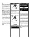
No smoke or soot should be present. These
logs are designed to be involved in the fire.
Flames will impinge the top tips of the right
and left logs.
If the logs are properly positioned and soot
-
ing conditions exist, the air shutter opening
on the main burner tube should be adjusted.
Normally, the more offsets in the vent system,
the greater the need for the air shutter to be
opened further.
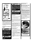
CAUTION
The air shutter and appliance
surfaces are hot. Exercise caution
to avoid injury while adjusting
air shutter.
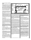
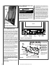
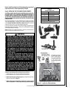
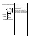
ELECTRONIC
Flame
Sensor
Hood
Igniter Rod
Pilot
Nozzels
Figure 49
Figure 48
MILLIVOLT
Thermocouple
Hood
Igniter Rod
3/8" Min
(9 mm)
Thermopile
Pilot
Nozzels
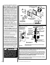
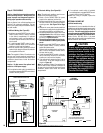
Step 10. CHECKING APPLIANCE OPERA-
TION
With gas line installed run initial system check-
out before closing up the front of the unit. Follow
the pilot lighting instructions provided in the
Care and Operation Manual. For piezo igniter
location see
Figure 39 on Page 24 (millivolt
appliances only).
Note: Lighting Instructions are also found on the
literature tag tied to the gas piping next to the
gas valve. To access the tag, open the bottom
control panel (see instruction sheet provided
with the facade kit for additional information
about the control panel). See Figure 39 on
Page 24.
When first lighting the appliance, it will take
a few minutes for the line to purge itself of
air. Once purging is complete, the pilot and
burner will light and operate as indicated in
the instruction manual. Subsequent lighting
of the appliance will not require such purging.
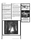
Inspect the pilot flame (remove logs, if neces
-
sary, handling carefully).
Millivolt Appliance Checkout
The pilot flame should be steady, not lifting
or floating. Flame should be blue in color with
traces of orange at the outer edge.
The top 3/8" (10 mm) at the pilot generator
(thermopile) and the top 1/8" minimum (tip)
of the quick drop out thermocouple should be
engulfed in the pilot flame.
The flame should project 1" (25 mm) beyond
the pilot hood at all three ports
(Figure 48).
Replace logs if removed for pilot inspection.
To light the burner; rotate the gas valve control
knob counterclockwise to the “ON” posi
-
tion and turn “ON” the appliance mounted
ON/OFF switch (or optional remote switch, if
installed).
Electronic Appliance Checkout
To light the burner, turn ‘ON’ the unit mounted
On/Off switch or the optional remote wall switch.
Ensure the igniter lights the pilot. The pilot
flame should engulf the flame rod as shown
in
Figure 49.