


12
NOTE: DIAGRAMS & ILLUSTRATIONS ARE NOT TO SCALE.
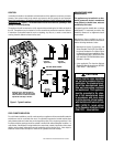
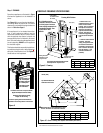
Figure 13
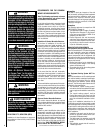
Step 3. INSTALL THE VENT SYSTEM
General Information
These instructions should be used as a guide-
line and do not supersede local codes in any
way. Install vent according to local codes,
these instructions, the current National Fuel
Gas Code (ANSI-Z223.1) in the USA or the cur
-
rent standards of CAN/CSA-B149 in Canada.
These fireplaces are designed, tested and
listed for operation and installation with,
and only with, Secure Vent™ Direct Vent
System Components, Secure Flex™ Flexible
Vent Components manufactured by Security
Chimneys International and Z-FLEX™
Model
GA Venting Systems listed to UL1777 and
ULCS635 manufactured by Flexmaster Canada
Limited. These approved vent system compo-
nents are labeled for identification. DO NOT
use any other manufacturer's vent components
with these appliances.
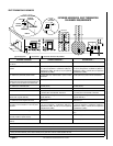
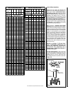
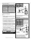
Vertical (Straight) Installation
Determine the number of straight vent sections
required. 4-1/2" (114 mm), 10-1/2" (267 mm),
22-1/2" (572 mm), 34-1/2" (876 mm) and 46-
1/2" (1181 mm) net section lengths are available.
Plan the vent lengths so that a joint does not
occur at the intersection of ceiling or roof joists.
Refer to the Vent Section Length Chart.
These fireplaces must be vented directly
to the outside.
The vent system may not service multiple
appliances, and must never be connected to a
flue serving a solid fuel burning appliance. The
vent pipe is tested to be run inside an enclosing
wall (such as a chase). There is no requirement
for inspection openings in the enclosing wall at
any of the joints in the vent pipe.
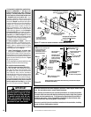
Select Venting System - Horizontal or Verti-
cal
With the appliance secured in framing, de-
termine vent routing and identify the exterior
termination location. The following sections
describe vertical (roof) and horizontal (exterior
wall) vent applications. Refer to the section
relating to your installation. A list of approved
venting components are shown in the tables
on Page 30.
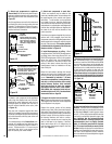
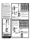
VERTICAL TERMINATION SYSTEMS (ROOF)
Figures 17, and 23 through 25 on Pages
14 and 16 and their associated Vertical
Vent Tables illustrate the various vertical venting
configurations that are possible for use with
these appliances. Secure Vent pipe applications
are shown in these figures; Secure Flex pipe
may also be used.
A Vertical Vent Table summarizes each system’s
minimum and maximum vertical and horizontal
length values that can be used to design and
install the vent components in a variety of
applications.
Both these vertical vent systems terminate
through the roof. The minimum vent height
above the roof and/or adjacent walls is speci-
fied in ANSI Z223.1-(latest edition) (In Canada,
the current CAN/CSA-B149 installation code)
by major building codes. Always consult your
local codes for specific requirements. A general
guide to follow is the Gas Vent Rule (refer to
Figure 6 on Page 8).
SV4.5H
T -2
T ermination
SV4.5F A OR
SV4.5FB Flashing
AND SV4.5SC
STORM COLLAR
SV4.5VF
Firestop/Spacer
SV4.5L6/12/24/36/48
V ent Sections
40' Max.
(12.2 M)
6' Min.
(1.8 M)
1" (25.4 mm)
Minimum
Clearance to
Combustibles
When using Secure
Flex,
use Firestop/Spacer
SF4.5VF
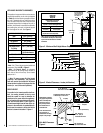
Figure 12
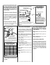
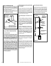
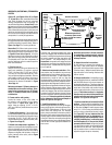
Step 2. ROUTING GAS LINE
Route a 1/2" (13 mm) gas line along the inside
of the left side framing as shown in
Figure 12.
Gas lines must be routed, constructed and made
of materials that are in strict accordance with
local codes and regulations.
All appliances are factory-equipped with a
flexible gas line connector and 1/2 inch shutoff
valve.
(See Step 7 on Page 24).
6-1/8"
(156 mm)
*1-7/8"
(65 mm)
Right Side Front
Corner of Fire-
place Framing
* Measured from the top of
platform that unit is installed on
to pipe center (see Figure 9)
FPO