


14
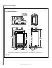
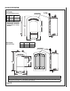
NOTE: DIAGRAMS & ILLUSTRATIONS ARE NOT TO SCALE.
G. Continue installation of horizontal/inclined
sections - Continue with the installation of the
straight vent sections in horizontal/inclined run
as described in
Step C. Install support straps
every 5' (1.52 m) along horizontal/inclined vent
runs using conventional plumber’s tape.
It is
very important that the horizontal/inclined
run be maintained in a straight (no dips) and
recommended to be in a slightly elevated
plane, in a direction away from the fireplace
of 1/4" rise per foot (20 mm per meter) which
is ideal, though rise per foot run ratios that are
smaller are acceptable all the way down to at or
near level. Use a carpenter’s level to measure
from a constant surface and adjust the support
straps as necessary.
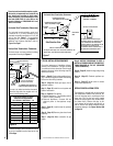
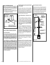
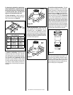
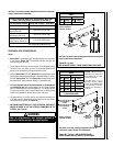
First Vent
Component
Align the dimple (four places)
with the opening of the locking
incline channel on appliance
collar. Twist vent component
clockwise to engage and seal.
Locking
Incline Channel
Dimple
Appliance collar
Vent / Appliance Collar
Connection
Align the dimple (four places) of the
upper vent section with the opening of
the locking incline channel on the
lower vent section. Twist vent
component clockwise to engage and
seal until arrow and dimple align.
Locking
Incline Channel
Dimple
Arrow
Connected
Vent Sections
Vent / Vent Section
Connection
Arrow
Arrow
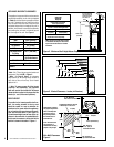
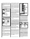
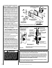
To attach a vent component to the appliance
collar, align the dimpled end over the collar,
adjusting the radial alignment until the four
locking dimples are aligned with the inlet of
the four inclined channels on the collar (
refer
to Figure 15).
Push the vent component against the collar
until it fully engages, then twist the component
clockwise, running the dimples down and along
the incline channels until they seat at the end
of the channels.
The unitized design of the
Secure Vent com-
ponents will engage and seal both the inner
and outer pipe without the need for sealant or
screws. If desired a #6 x 1/2" screw may be
used at the joint, but it is not required as the
pipe will securely lock when twisted.
Figure 15
Figure 17
Figure 16
C. Attach vent components to each other
- Other vent sections may be added to the
previously installed section in accordance with
the requirements of the vertical vent figures
and tables. To add another vent component
to a length of vent run, align the dimpled end
over the inclined channel end of the previously
installed section, adjusting the radial alignment
until the four locking dimples are aligned with
the inlets of the four incline channels of the
previous section.
Push the vent component against the previous
section until it fully engages, then twist the
component clockwise running the dimples down
and along the incline channels until they seat at
the end of the channels.
This seating position
is indicated by the alignment of the arrow and
dimple as shown in Figure 16.
D. Install firestop/spacer at ceiling - When
using Secure Vent, use SV4.5VF firestop/spacer
at ceiling joists; when using Secure Flex, use
SF4.5VF firestop/spacer. If there is living space
above the ceiling level, the firestop/spacer
must be installed on the bottom side of the
ceiling. If attic space is above the ceiling, the
firestop/spacer must be installed on the top
side of the joist.
Route the vent sections through the framed
opening and secure the firestop/spacer with
8d nails or other appropriate fasteners at each
corner.
Remember to maintain 1" (25 mm)
clearance to combustibles, framing members,
and attic or ceiling insulation when running
vertical chimney sections. Attic insulation
shield may be used to obtain the required
clearances indicated here (order H3907,
SV4.5ARSA, Attic insulation shield with ad-
justable height from 12"-22"). See installation
accessories table on Page 30.
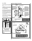
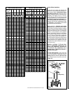
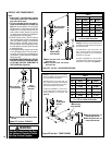
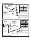
E. Support the vertical vent run sections -
Note - Proper venting support is very important.
The weight of the vent must not be supported
by the fireplace in any degree.
Support the vertical portion of the venting
system every 8 feet (2.4m) above the fireplace
vent outlet. One method of support is by utiliz
-
ing field provided support straps (conventional
plumber's tape). Secure the plumber's tape to
the framing members with nails or screws.
Loop the tape around the vent, securing the
ends of the tape to the framing. If desired,
sheet metal screws #6 x 1/2" length may be
used to secure the support straps to the vent
pipe. See
Figure 17.
B. Attach vent components to appliance
- Secure Vent SV4.5 direct vent system compo-
nents are unitized concentric pipe components
featuring positive twist lock connections (
see
Figure 15).
All of the appliances covered in this document
are fitted with collars having locking inclined
channels. The dimpled end of the vent compo
-
nents fit over the appliance collar to create the
positive twist lock connection.
Blocking
Support Straps
(Plumber's tape)
8 feet (2.4 m)
Maximum
1 inch (25.4
mm) minimum
clearance to
combustibles
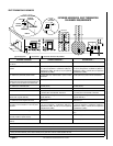
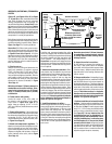
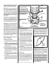
F. Change vent direction to horizontal/inclined
run - At transition from or to a horizontal/in-
clined run, install the SV4.5E45 and SV4.5E90
elbows in the same manner as the straight vent
sections. The elbows feature a twist section to
allow them to be routed about the center axis
of their initial collar section to align with the
required direction of the next vent run element.
Twist elbow sections in a clockwise direction
only so as to avoid the possibility of unlocking
any of the previously connected vent sections.
See
Figure 18.
Figure 18
7-5/8”
(194 mm)
4-13/16
(122 mm)
Swivel Joint
(360° swivel)
SV4.5E45
45° Elbow)
Swivel Joint
(360° swivel)
SV4.5E90
90° Elbow)
(206 mm)
8-1/8"