


8
Vent Restriction
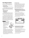
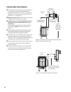
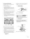
The GF 600 DV Firelight includes two rectangular
Exhaust Restrictor plates and one square Air Inlet
Restrictor Plate as shown in Figure 5. These are
located in the parts bag. The plates are used to
compensate for draft characteristics that would
otherwise interfere with proper burner perfor-
mance such as low heat output, weak flame
picture, or inefficient combustion.
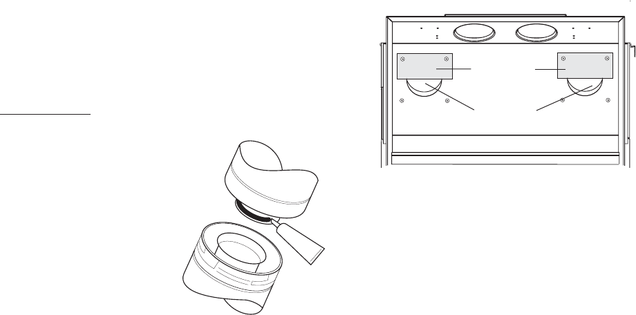
Exhaust Restrictor Plate Installation
• Both Exhaust Restrictor Plates (#129642) MUST
be installed in all Co-linear vent systems and any
vertically terminated vent run exceeding 7 feet
(210 cm) in length.
1. Remove the Glass Panel and Log Set.
2. Using a 1/4” nut driver, remove the two sheet
metal screws in the rear wall of the firebox
ABOVE EACH exhaust outlet. See Figure 5.
3. Install a restrictor plate over the upper half of
each exhaust hole and secure the plate using the
same screws that were just removed.
4. Reinstall logs and glass.
SEALANT
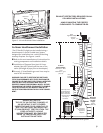
Vent Requirements
There are three types of venting configurations
approved for use with the Firelight gas stove:
• Vertical Termination
• Hearthmount Co-Linear (Vertical Termination)
• Horizontal Termination
The GF600 Firelight is approved for use with the
vent systems listed below. Use parts of one manu-
facturer only - DO NOT MIX VENT COMPONENTS
FROM DIFFERENT MANUFACTURERS IN THE SAME
SYSTEM.
• Simpson Dura-Vent GS
• Amerivent Corporation
• Security Vent Ltd.
• Selkirk Metalbestos
Installation of any components not manufac-
tured or approved by Jøtul or failure to meet all
clearance requirements will void all warranties and
could result in property damage or bodily injury.
The approved vent configurations described in
this manual are derived from extensive testing
under controlled laboratory conditions. Gas appli-
ance performance can be negatively affected by
variables present in the installation environment, i.e:
atmospheric pressure, strong prevailing winds,
adjacent structures and trees, snow accumulation,
etc. These conditions should be taken into consider-
ation by the installer and stove owner when plan-
ning the vent system design.
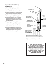
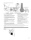
IMPORTANT
• JOINT SEALING REQUIREMENT:
Apply a 1/8” bead of high-
temperature (750°F) sealant to
the male section of the inner
vent pipe. See Fig. 9. The
cement should form a seal
between the inner and
outer pipes.
• NEVER modify any
venting component or
use a damaged venting
component.
• The gas appliance and vent system must be
vented directly to the outside of the building and
never attached to a chimney serving a solid fuel
or other gas appliance. Each direct vent gas
appliance must have its own separate vent
system. Common vent systems are prohibited.
• If the venting system is disassembled for any
reason, re-install according to the manufacturer’s
installation instructions.
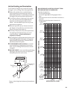
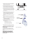
Air Inlet Restrictor Plate Installation
• The Air Inlet Restrictor (#129347) MUST be in-
stalled with any Co-linear Vent system.
1. Remove the Glass Panel and Log Set.
2. Using a 1/4” nut driver, remove the two sheet
metal screws (A) and Rear Log Shelf from the back
of the firebox. See Figure 6.
3. Using the right hand sheet metal screw, reinstall
the Log Shelf with the restrictor plate between
the Shelf and the Back Wall. The plate should
cover the lower right air inlet.
4. Reinstall logs and glass.
Restrictor
Plate
Exhaust
Outlet
Figure 5. Exhaust Restrictor Plate installation.