22
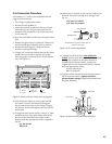
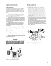
3. BURNER ADJUSTMENT: The Jøtul GF 600 DV
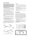
Firelight gas stove is equipped with a variable
gas control valve that provides easy adjustment
of the flame height, appearance, and heat
output. To adjust the flame between the HI and
LOW setting, rotate the HI/LOW knob, located in
the center of the valve face. Flame height will
adjust approximately 1.0” to 1.5” between the
LOW and HIGH settings. See Fig. 24.
NO SMOKE OR SOOT SHOULD BE PRESENT.
CHECK LOG PLACEMENT IF ANY SOOT OR SMOKE IS
DETECTED. IF SOOT OR SMOKE PERSISTS, THE AIR
SHUTTER MAY NEED TO BE ADJUSTED.
See Air Shutter/Flame Appearance section of
this manual for proper air shutter settings and
adjustments. Note: the more offsets there are in
the vent system, the greater the need for an air
shutter adjustment. See page 19.
WARNING:
AIR SHUTTER ADJUSTMENTS SHOULD
ONLY BE PERFORMED BY A QUALIFIED
PROFESSIONAL SERVICE TECHNICIAN.
CAUTION:
DO NOT ATTEMPT TO ALTER THE FLAME
APPEARANCE BY POSITIONING THE GAS
VALVE IN ANY OTHER POSITION OTHER
THAN THE FULL “ON” POSITION.
Optional Blower Kit Installation
1. Unpack the blower kit. Use a 10mm wrench to
remove the Mounting Bracket from the Blower.
Keep the nuts and tooth washers for reassembly.
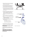
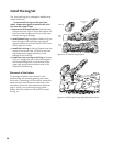
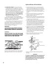
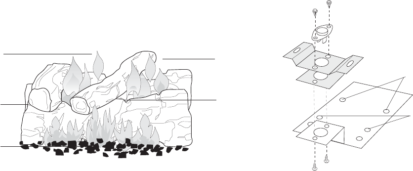
2. Attach the Snapstat to the Snapstat Retainer
using two #7 x 3/8” phillips screws supplied. See
fig. 25.
3. Attach the Snapstat Retainer to the Mounting
Bracket using the remaining two #7 x 3/8”
phillips screws as in fig. 25.
4. Locate the two raised bosses on the bottom back
of the stove. The blower is mounted to the stove
using these two threaded holes.
5. Use the two M6 x12 mm hex head flange bolts to
attach the Mounting Bracket to the base of the
stove. Orient the bracket with the Snapstat toward
the front of the stove and align the two MIDDLE
mounting holes on the bracket with the two
threaded holes on the bottom back of the stove.
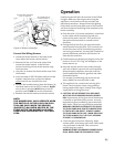
6. Position the blower with the junction box to the
REAR of the stove and insert the two threaded
studs on the blower through the rear-most holes
in the blower bracket. Attach the blower to the
bracket using the nuts and washers previously
removed. See fig. 26.
7. Attach either black and white wire from the
blower to either Snapstat terminal.
WARNING:
The blower is equipped with a three-prong (ground-
ing) plug for protection against shock hazard and
must be plugged directly into a properly grounded
three-prong receptacle. Do not cut or remove the
grounding prong from the plug.
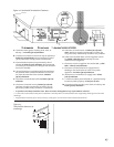
Figure 24. Flame appearance on the “high” setting
after approximately 15 to 20 minutes operation.
5”
4”
4”
Figure 25. Snapstat / Blower Mounting Bracket
assembly.
Mounting
Bracket
Snapstat Retainer
Snapstat
Stove Attachment
Blower Attachment


