


16
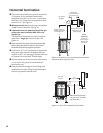
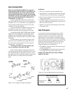
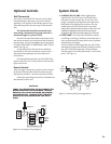
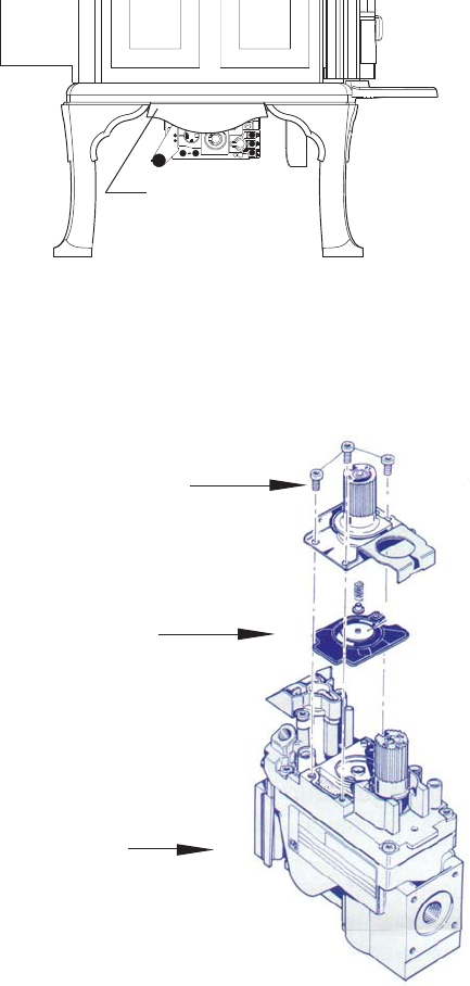
17. Replace the variable regulator. Using a Torx T-20
screwdriver, remove the three specialty screws
from the HI/LO regulator on the front of the
valve. Note: To help identify which screws to
remove, refer to the new regulator in the kit. See
Figure 16.
18. Remove the regulator tower and the gasket. Be
sure to remove the black rubber gasket from the
valve.
19. Install the new variable regulator tower from the
kit. Be sure that the gasket is properly positioned
and tighten screws securely.
20. Install the identification labels to the stove so
that they can be seen by any person that may be
servicing the stove.
Label A: Apply to back of stove.
Label B: Apply to the Rating Plate.
Small valve sticker: Apply to valve.
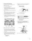
13. Replace the burner tube (19), front log support
(18) and air divider (21), be sure to secure with
the two 1/4” hex head screws.
14. Install the log set (36), embers and glass assem-
bly (16). See page 18 for log set placement.
15. Reinstall the top panel (6) and top griddle (7).
Be sure to secure with set screws from step 3.
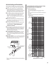
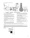
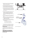
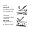
16. Locate the decorative cast iron skirt (4) between
the left front and rear legs. Use a 13 mm wrench
or socket to remove the bolt that secures the skirt
to the base of the stove to improve access to the
valve. See Fig. 15.
21. Reassemble the stove, apply gas to the system
and check for leaks using a soapy water solution.
NEVER USE AN OPEN FLAME TO CHECK
FOR GAS LEAKS.
It is important that the correct gas pressure be
established at the time of installation. For more
details see the Gas Pressure section of this manual
(page 17).
ALWAYS REFER TO THE LIGHTING IN-
STRUCTIONS ON THE INSIDE BACK
COVER OF THIS MANUAL WHEN LIGHT-
ING THE STOVE.
Decorative Skirt
Figure 15. Remove the valve skirt for better access.
MAIN GAS VALVE
Figure 16. Regulator parts.
BE SURE TO
REMOVE THE BLACK
RUBBER GASKET
FROM THE VALVE!
VARIABLE
REGULATOR TOWER