


21
Optional Controls
Wall Thermostat
Use only a 750 millivolt DC two-wire circuit ther-
mostat, placed in the same room as the heater,
typically 5’ off the floor. Avoid drafty areas or any
area that may affect the accuracy of the thermo-
stat.
The thermostat should be connected to the
stove using a minimum of 16 gauge wire with a
maximum length of 35 feet of wire.
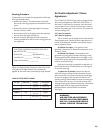
Connect the two thermostat wire leads to the
two lower terminals on the terminal block located
ont the valve. Do not overtighten the connections.
IT IS NOT NECESSARY TO DISCONNECT ANY OTHER
WIRES. See Fig. 22.
At the thermostat, the two wires should be
connected to the two connection screws on the
thermostat base plate per the manufacturer’s
instructions.
For thermostatic operation, the On/Off/T-Stat
switch must be in the T-stat position, and the pilot
light must be on.
Remote Control
When using a remote, the remote receiver should
be wired to the terminal block the same way the
thermostat would be. See the instructions above.
Follow the operating instructions included with
the Remote Control unit.
CAUTION:
LABEL ALL WIRES PRIOR TO DISCONNECTION
WHEN SERVICING THE CONTROLS. WIRING
ERRORS CAN CAUSE IMPROPER OR DANGER-
OUS OPERATION. ALWAYS VERIFY PROPER
OPERATION AFTER SERVICING THE APPLI-
ANCE.
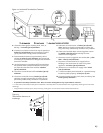
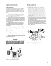
Figure 22. Accessory wiring diagram.
System Check
1. PURGING THE GAS LINE: When lighting the
appliance for the first time, it will take a few
moments to clear the gas line of air. Once this
purge is complete, the appliance will operate as
described in the lighting instructions. See the
inside back cover of this manual or the stove
Rating Plate attached the bottom of the stove. All
subsequent lightings of the stove will not require
purging the gas line unless the supply line is shut off.
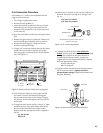
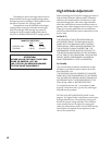
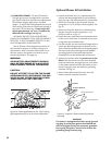
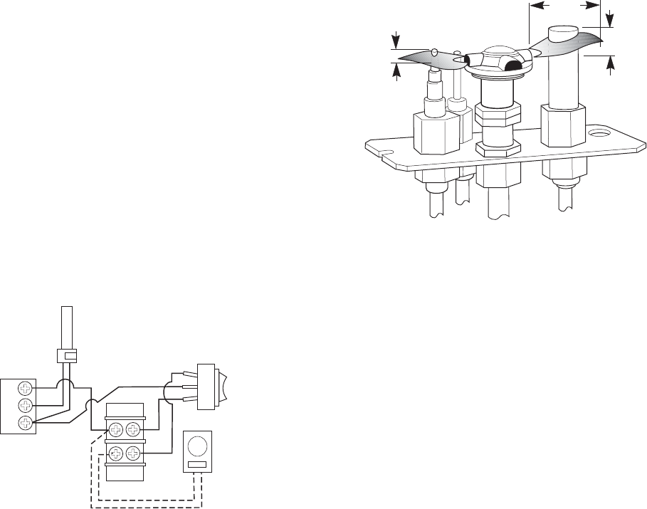
2. PILOT FLAME: The pilot flame should be steady -
not lifting or floating. The flame should be blue in
color around the pilot hood, with traces of yellow
toward the outer edges.
The pilot flame should engulf the top 3/8” of the
thermopile (to generate millivolt current) and the
top 1/8” of the thermocouple. The pilot flame
should project out of the pilot hood 1” at all three
ports. See Figs. 23.
1
(25mm)
3/8
(8mm)
Min.
1/8
(3mm)
Min.
Figure 23. Correct pilot flame appearance.
TERMINAL
BLOCK
VALVE
THERMOPILE
OPTIONAL
THERMOSTAT
or
REMOTE
CONTROL
TH
TP
TH
TP
ROCKER
SWITCH
ON
OFF
STAT