


364861-UIM-H-0712
Johnson Controls Unitary Products 9
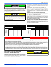
SECTION III: FILTERS
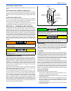
FILTER INSTALLATION
All applications require the use of a field installed filter. All filters and
mounting provision must be field supplied.
Filters must be installed external to the furnace cabinet. DO NOT
attempt to install filters inside the furnace.
1.Air velocity through throwaway type filters may not exceed 300 feet per min-
ute (91.4 m/min). All velocities over this require the use of high velocity fil-
ters.
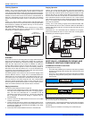
2.Do not exceed 1800 CFM using a single side return and a 16x25 filter. For
CFM greater than 1800, you may use two side returns or one side and the
bottom or one side return with a transition to allow use of a 20x25 filter.
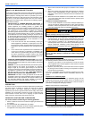
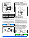
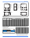
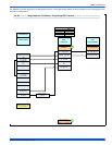
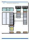
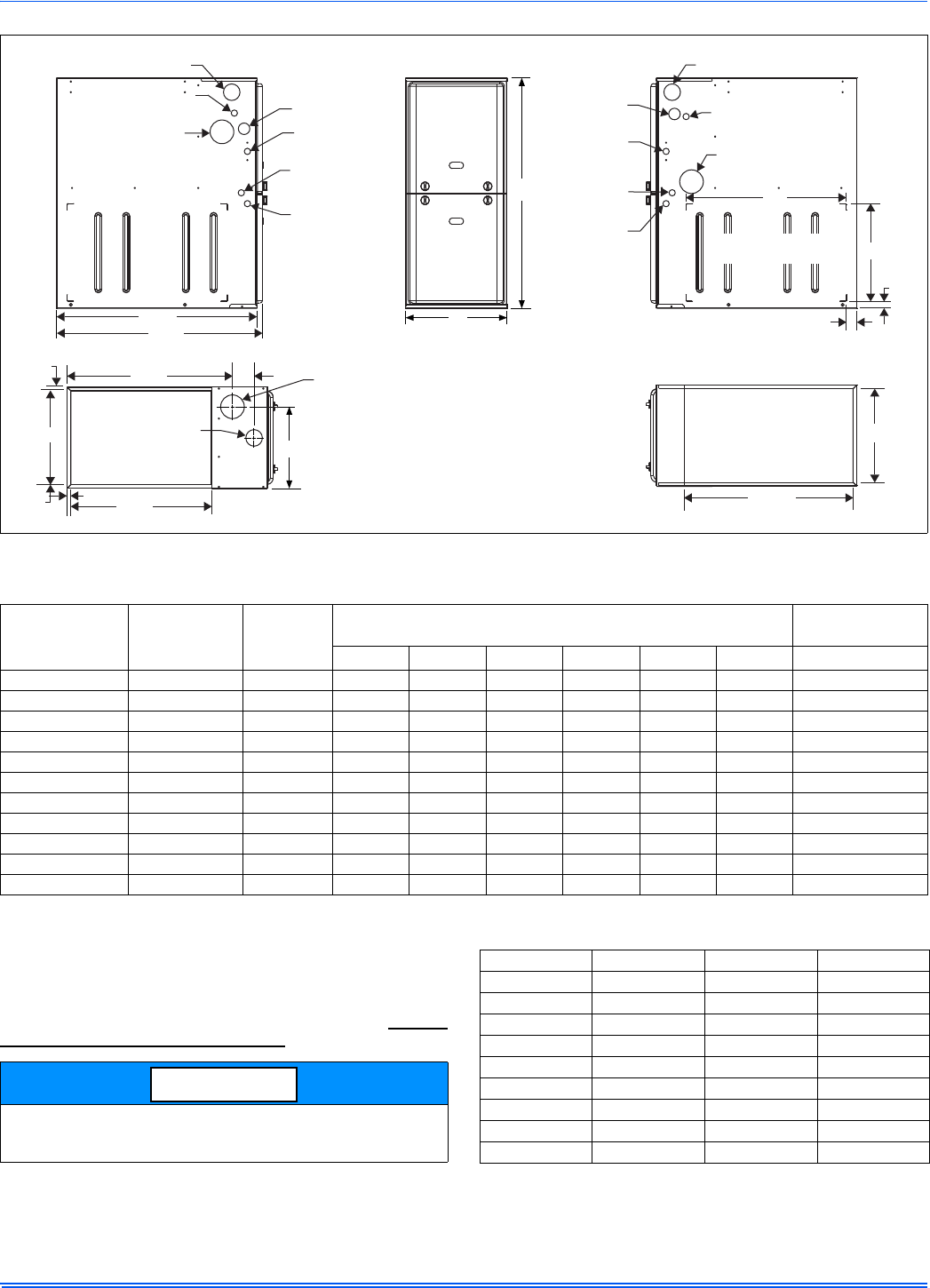
FIGURE 13: Dimensions
FRONT
33
A
LEFT SIDE
CombustionAir Inlet
Condensate Drain
(Downflow)
Vent Outlet
Thermostat
Wiring
28.5”
Gas Pipe
Entry
Electrical
Entry
Condensate
Drain
Thermostat
Wiring
RIGHT SIDE
Vent Outlet
Condensate Drain
(Downflow)
14”
1”
1.5”
23”
CombustionAir Inlet
Gas Pipe
Entry
Electrical
Entry
Condensate
Drain
Optional Return Air
Cutout (Either side)
29.5”
(For Claddeddoor add appoximately anadditional .75”)
C
SUPPLY END
.56”
.56”
20”
B
3”
23.8”
.56”
Combustion
Air Inlet
Vent
Outlet
RETURN END
B
24.25”
Table 3: Cabinet and Duct Dimensions
BTUH (kW)
Input
Nominal
CFM (m
3
/min)
Cabinet
Size
Cabinet Dimensions (Inches)
Approximate
Operating Weights
A (in) A (cm) B (in) B (cm) C (in) C (cm) Lbs (kg)
40 (11.7) 800 (22.7) A 14 1/2 36.8 13 3/8 34.0 11 3/4 29.8 113 (51.3)
60 (17.6) 1000 (28.3) A 14 1/2 36.8 13 3/8 34.0 11 3/4 29.8 118 (53.5)
60 (17.6) 1200 (34.0) B 17 1/2 44.4 16 3/8 41.6 13 1/4 33.7 122 (55.3)
80 (23.4) 1200 (34.0) B 17 1/2 44.4 16 3/8 41.6 14 3/4 37.5 126 (57.2)
80 (23.4) 1600 (45.3) C 21 53.3 19 7/8 50.5 16 1/2 41.9 136 (61.7)
80 (23.4) 2200 (62.3) C 21 53.3 19 7/8 50.5 16 1/2 41.9 139 (63.0)
100 (29.3) 1600 (45.3) C 21 53.3 19 7/8 50.5 18 1/4 46.4 142 (64.4)
100 (29.3) 2000 (56.6) C 21 53.3 19 7/8 50.5 18 1/4 46.4 145 (65.8)
120 (35.1) 1600 (45.3) D 24 1/2 62.2 23 3/8 59.4 21 3/4 55.2 153 (69.4)
120 (35.1) 2000 (56.6) D 24 1/2 62.2 23 3/8 59.4 21 3/4 55.2 156 (70.7)
130 (38.1) 2000 (56.6) D 24 1/2 62.2 23 3/8 59.4 No Hole No Hole 160 (72.5)
Single side return above 1800 CFM is approved as long as the filter
velocity does not exceed filter manufacturer’s recommendation and a
transition is used to allow use on a 20x25 filter.
NOTICE
Table 4: Recommended Filter Sizes (High Velocity 600 FPM)
CFM (m³/min) Cabinet Size Side (in) Bottom (in)
800 (22.7) A 16 x 25 14 x 25
1000 (28.3) A 16 x 25 14 x 25
1200 (34.0) A 16 x 25 14 x 25
1200 (34.0) B 16 x 25 16 x 25
1600 (45.3) B 16 x 25 16 x 25
1600 (45.3) C 16 x 25 20 x 25
2000 (56.6) C (2) 16 x 25 20 x 25
2200 (62.3) C (2) 16 x 25 20 x 25
2000 (56.6) D (2) 16 x 25 22 x 25