


364861-UIM-H-0712
Johnson Controls Unitary Products 7
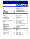
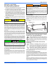
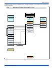
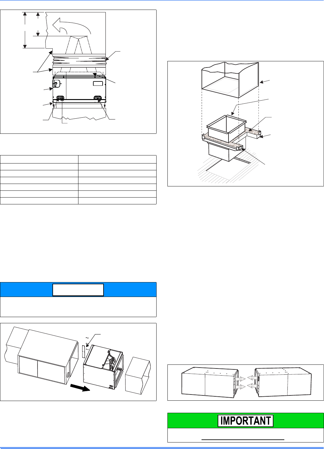
Dimension “C” should be at least 2/3 of dimension “D”. See Figure 6.
CRITICAL COIL PROJECTION
The coil assembly must be located in the duct such that a minimum dis-
tance is maintained between the top of the coil and the top of the duct.
Refer to Table 2.
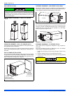
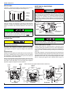
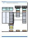
COIL / FURNACE ASSEMBLY - HC SERIES COILS
These coils are supplied ready to be installed in a right hand position or
a left hand position. When used in conjunction with a horizontal furnace
(blow through) application, the coil should be oriented with the opening
of the “A” coil closest to the furnace. See Figure 7.
DOWNFLOW DUCT CONNECTORS
All downflow installations must use a suitable duct connector approved
by the furnace manufacturer for use with this furnace. The duct connec-
tors are designed to be connected to the rectangular duct under the
floor and sealed. Refer to the instructions supplied with the duct con-
nector for proper installation. Refer to the separate accessory parts list
at the end of these instructions for the approved accessory duct con-
nectors.
RESIDENTIAL AND MODULAR HOME UPFLOW
RETURN PLENUM CONNECTION
Return air may enter the furnace through the side(s) or bottom depend-
ing on the type of application. Return air may not be connected into the
rear panel of the unit.
SIDE RETURN APPLICATION
Side return applications pull return air through an opening cut in the
side of the furnace casing. This furnace is supplied with a bottom block-
off panel that should be left in place if a side return is to be used. If the
furnace is to be installed on a flat, solid surface, this bottom panel will
provide an adequate seal to prevent air leakage through the unused
bottom opening. However, if the furnace is to be installed on a surface
that is uneven, or if it is to be installed on blocks or otherwise raised off
the floor, it will be necessary to seal the edges of the bottom panel
to the casing using tape or other appropriate gasket material to
prevent air leakage.
BOTTOM RETURN AND ATTIC INSTALLATIONS
Bottom return applications normally pull return air through a base plat-
form or return air plenum. Be sure the return platform structure or return
air plenum is suitable to support the weight of the furnace.
The internal bottom panel must be removed for this application.
Attic installations must meet all minimum clearances to combustibles
and have floor support with required service accessibility.
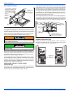
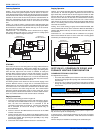
HORIZONTAL APPLICATION
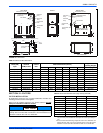
FIGURE 6: PC Series Upflow Coil Installation
Table 2: Coil Projection Dimensions - PC Series Coils
COIL SIZE DIMENSION “C” INCH
PC18 3-1/2
PC24 4-1/2
PC30, PC32, PC35 4-1/2
PC42, PC43, PC36, PC37 5-1/2
PC48 6-1/2
PC60 9
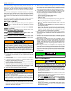
Each coil is shipped with an external tie plate that should be used to
secure the coil to the furnace. It should be installed on the back side
of the coil using the dimpled pilot holes. See Figure 7.
FIGURE 7: Horizontal Left or Right application (Right Shown)
Flexible
Duct Collar
Do not drill
or Screw
this flange
Field
Fabricated
Ductwork
Upflow
Coil
Upflow
Furnace
Secondary
Drain
Primary
Drain
D
C
(Min)
Alternate
Drain Location
NOTICE
Use tie plate
supplied with coil
Air flow
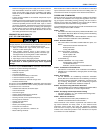
Gas Furnace
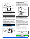
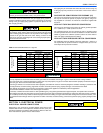
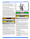
FIGURE 8: Combustible Floor Base Accessory
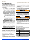
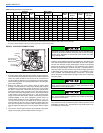
FIGURE 9: Horizontal Application
This furnace may be installed in a horizontal position on either side as
shown above. It must not be installed on its back.
FURNACE
WARMAIRPLENUM
WITH 1”FLANGES
FIBERGLASS
INSULATION
FIBERGLASSTAPE
UNDER FLANGE
COMBUSTIBLE FLOOR
BASEACCESSORY