


364861-UIM-H-0712
16 Johnson Controls Unitary Products
Twinning Operation
Heating - On a call for heat (W signal) from the wall thermostat, both
furnaces will start the ignition sequence and the burners on both fur-
naces will light. About thirty seconds after the burners light, the blowers
on both furnaces will come on in heating speed. When the thermostat is
satisfied, the burners will all shut off and, after the selected blower off
delay time, both blowers will shut off at the same time. The twinning
control ensures that both blowers come on and shut off at the same
time.
Cooling - On a call for cooling (Y signal) from the wall thermostat, both
furnace blowers will come on at the same time in cooling speed. When
the thermostat is satisfied, both blowers will stay on for 60 seconds,
then will shut off at the same time.
Continuous Fan - On a thermostat call for continuous fan (G signal),
both furnace blowers will come on at the same time in cooling speed
and will stay on until the G signal is removed.
STAGING
This control can also be used along with a two-stage wall thermostat to
stage two twinned furnaces, making them operate like a single two-
stage furnace. This allows only one furnace to supply heat during times
when the heat output from one furnace is sufficient to satisfy the
demand. When one duct system is used for two furnaces, it is neces-
sary that the two blowers operate in unison. The twinning function of
this board ensures that both blowers turn on and off simultaneously,
and operate on the same blower speed. Even when only one furnace is
supplying heat, both furnace blowers must run.
The twinning feature of this board can also be used for staging of two
furnaces. With this feature, a single wire is connected between the
TWIN terminal on one furnace board to the TWIN terminal on the sec-
ond furnace board. The board then communicates the blower status
from one furnace to the other along this wire. This communication
makes the second furnace blower come on at the same time, and on
the same speed, as the first furnace blower. To ensure stable communi-
cation, the common terminal of each control must be connected.
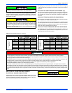
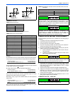
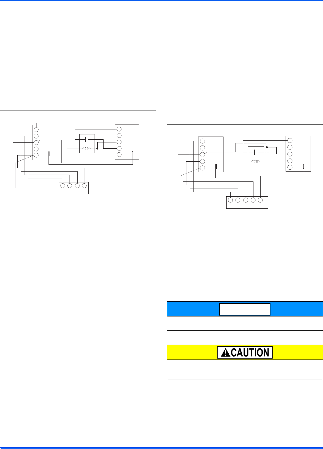
Staging Instructions
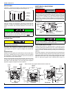
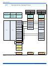
Connect the control wiring as shown in Figure 22.
1. Connect the low voltage wiring from the wall thermostat to the ter-
minal strip on the control board of Furnace #1. For staging applica-
tions, the wire from thermostat W1 is connected to the W
connection on the board on Furnace #1. The wire from thermostat
W2 is connected to Furnace #2 through a separate relay, as
described below.
2. Connect a wire from the TWIN terminal of Furnace #1 to the TWIN
terminal of Furnace #2.
3. Install a separate 24V relay as shown in the diagram below. Use of
this relay is required, as it ensures that the transformers of the two
furnaces are isolated, thus preventing the possibility of any safety
devices being bypassed.
4. Connect the 24V common between furnace #1 and furnace #2.
Staging Operation
Heating - On a call for first-stage heat (W1 signal) from the wall thermo-
stat, Furnace #1 will start the ignition sequence and the burners will
light. About thirty seconds after the burners light, the blowers on both
furnaces will come on in heating speed. When the thermostat is satis-
fied, the burners will shut off and, after the selected blower off delay
time, both blowers will shut off at the same time. On a call for second
stage of heat, the burners of Furnace #2 will also light and both blowers
will run. The twinning control ensures that both blowers come on and
shut off at the same time.
Cooling - On a call for cooling (Y signal) from the wall thermostat, both
furnace blowers will come on at the same time. When the thermostat is
satisfied, both blowers will stay on for 60 seconds, then will shut off at
the same time.
Continuous Fan - On a thermostat call for continuous fan (G signal),
both furnace blowers will come on at the same time in cooling speed
and will stay on until the G signal is removed.
SECTION VII: CONDENSATE PIPING AND
FURNACE VENTING CONFIGURATION
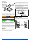
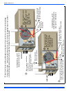
CONDENSATE DRAIN LOCATION
As shipped from the factory:
• For all 040, 060, & 080K input furnaces the main drain is plumbed
through the casing right-side opening when viewed from the front
of the furnace.
• For all 100, 120, & 130K input furnaces the main drain is plumbed
through the casing left-side opening when viewed from the front
of the furnace.
The condensate hoses must slope downwards at all points.
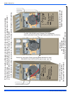
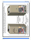
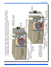
When drain hose routing changes are required (shown in Figures 25 -
28), be sure to cap all un-used openings.
If rerouting hoses - excess length should be cut off so that no sagging
loops will collect and hold condensate - which will cause the furnace to
not operate.
No hose clamps are needed for connecting to the condensate pan.
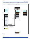
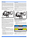
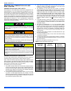
FIGURE 21: Twinning Wiring Diagram
W
G
C
R
Y
TWIN
TOA/C
WALL THERMOSTAT
WG
R
Y
ISOLATION
RELAY
FURNACE 2
CONTROL BOARD
W
G
C
R
Y
TWIN
FURNACE 1
CONTROL BOARD
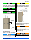
FIGURE 22: Staging Wiring Diagram
The Figures 25 - 28 show the condensate drain arrangement for the
various possible furnace and vent blower positions.
The furnace condensate pan is self priming and contains an internal
trap to prevent flue gas leaking. Do not install an external condensate
trap.
W
G
C
R
Y
TWIN
TOA/C
WALL THERMOSTAT
W1 G
R
Y
ISOLATION
RELAY
FURNACE 2
CONTROL BOARD
W
G
C
R
Y
TWIN
FURNACE 1
CONTROL BOARD
W2
NOTICE