


364861-UIM-H-0712
36 Johnson Controls Unitary Products
SECTION X: SAFETY CONTROLS
CONTROL CIRCUIT FUSE
A 3-amp fuse is provided on the control circuit board to protect the 24-
volt transformer from overload caused by control circuit wiring errors.
This is an ATO 3, automotive type fuse and is located on the control
board.
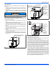
BLOWER DOOR SAFETY SWITCH
This unit is equipped with an electrical interlock switch mounted in the
burner compartment. This switch interrupts all power at the unit when
the panel covering the blower compartment is removed.
Electrical supply to this unit is dependent upon the panel that covers the
blower compartment being in place and properly positioned.
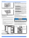
ROLLOUT SWITCH CONTROLS
These controls are mounted on the burner assembly. If the temperature
in the area surrounding burner exceeds its set point, the gas valve is
de-energized. The operation of this control indicates a malfunction in
the combustion air blower, heat exchanger or a blocked vent pipe con-
nection. Corrective action is required. These are manual reset controls
that must be reset before operation can continue.
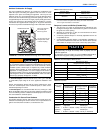
PRESSURE SWITCHES
This furnace is supplied with two pressure switches, which monitor the
flow through the combustion air/vent piping and condensate drain sys-
tem. These switches de-energize the gas valve if any of the following
conditions are present. Refer to "CONDENSATE PIPING AND FUR-
NACE VENTING CONFIGURATION" for tubing connections.
1. Blockage of vent piping or terminal.
2. Failure of combustion air blower motor.
3. Blockage of combustion air piping or terminals.
4. Blockage of condensate drain piping.
LIMIT CONTROLS
There is a high temperature limit control located on the furnace vesti-
bule panel near the gas valve. This is an automatic reset control that
provides over temperature protection due to reduced airflow. This may
be caused by:
1. A dirty filter.
2. If the indoor fan motor should fail.
3. Too many supply or return registers closed or blocked off.
The control module will lockout if the limit trips 5 consecutive times. If
this occurs, control will reset & try ignition again after 1 hour.
SECTION XI: NORMAL OPERATION AND
DIAGNOSTICS
NORMAL OPERATION SEQUENCE
The following describes the sequence of operation of the furnace. Refer
to Owners Manual for component location.
Continuous Blower
Cooling/heating thermostats have a fan switch that has an ON and
AUTO position. In the ON position the thermostat circuit is completed
between terminals R and G. The motor will operate continuously on the
speed tap wire that is connected to the “HI COOL” cooling terminal on
the control board. To obtain a constant air circulation at lower flow rate,
change the high-speed wire to another lower speed wire.
Intermittent Blower - Cooling
Cooling/heating thermostats have a fan switch that has an ON and
AUTO position. In the AUTO position the thermostat circuit is completed
between terminals R and G when there is a call for cooling. The motor
will operate on the speed tap wire that is connected to the “HI COOL”
cooling terminal on the control board. The fan off setting is fixed at 60
seconds to improve cooling efficiency.
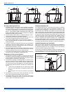
Heating Cycle
When the thermostat switch is set on HEAT and the fan is set on AUTO,
and there is a call for heat, a circuit is completed between terminals R
and W of the thermostat. When the proper amount of combustion air is
being provided, the pressure switch will close, the ignition control pro-
vides a 17-second ignitor warm-up period, the gas valve then opens,
the gas starts to flow, ignition occurs and the flame sensor begins its
sensing function. The blower motor will energize 30 seconds after the
gas valve opens, if a flame is detected. Normal furnace operation will
continue until the thermostat circuit between R and W is opened, which
causes the ignition system and gas valve to de-energize and the burner
flames to be extinguished. The vent motor will operate for 15 seconds
and the blower motor will operate for the amount of time set by the fan-
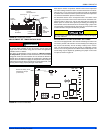
off delay jumper located on the control board. See Figure 42. The heat-
ing cycle is now complete, and ready for the start of the next heating
cycle.
If the flame is not detected within 7 seconds of the gas valve opening,
the gas valve is shut off and a retry operation begins. Also, if the flame
is lost for 2 seconds during the 10-second stabilization period, the gas
valve is shut off and a retry operation begins. During a retry operation,
the vent motor starts a 15 second inter-purge and the ignitor warm-up
time is extended to 27 seconds. If the flame is established for more than
10 seconds after ignition during a retry, the control will clear the ignition
attempt (retry) counter. If three retries occur during a call for heat, the
furnace will shut down for one hour. If at the end of the one hour shut
down there is a call for heat, the furnace will initiate a normal start cycle.
If the problem has not been corrected the furnace will again lockout
after three retries.
A momentary loss of gas supply, flame blowout, or a faulty flame probe
circuit will result in a disruption in the flame and be sensed within 1.0
seconds. The gas valve will de-energize and the control will begin a
recycle operation. A normal ignition sequence will begin after a 15 sec-
ond inter-purge. If during the five recycles the gas supply does not
return, or the fault condition is not corrected the ignition control will lock-
out for 60 minutes.
During burner operation, a momentary loss of power for 50 milliseconds
or longer will de-energize the gas valve. When the power is restored,
the gas valve will remain de-energized and the ignition sequence will
immediately restart.
TROUBLESHOOTING
The following visual checks should be made before troubleshooting:
1. Check to see that the power to the furnace and the ignition control
module is ON.
2. The manual shut-off valves in the gas line to the furnace must be
open.
3. Make sure all wiring connections are secure.
4. Review the sequence of operation. Start the system by setting the
thermostat above the room temperature. Observe the system’s
response. Then use the troubleshooting section in this manual to
check the system’s operation.
Main power to the unit must still be interrupted at the main power dis-
connect switch before any service or repair work is to be done to the
unit. Do not rely upon the interlock switch as a main power discon-
nect.
Blower and burner must never be operated without the blower panel
in place.
Never bypass any safety control to allow furnace operation. To
do so will allow furnace to operate under potentially hazardous
conditions.
Do not try to repair controls. Replace defective controls with
UPG Source 1 Parts.
Never adjust pressure switch to allow furnace operation.