


364861-UIM-H-0712
26 Johnson Controls Unitary Products
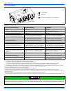
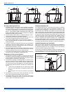
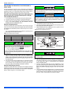
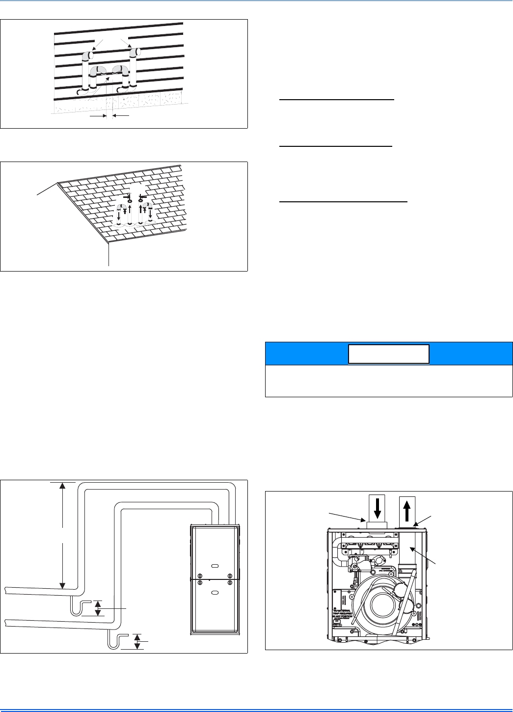
DOWNWARD VENTING
In some applications, it may be necessary to run the vent pipe and air
intake downwards. If this is to be done, the following rules must be fol-
lowed.
• A condensate trap hose must be connected to both the air intake
pipe and the vent pipe at the lowest part of the horizontal run.
• The condensate drain trap must have a trap of a minimum of six
inches.
• The total vertical downward distance must not exceed sixteen
feet.
• The condensate drain hose must be connected to a condensate
drain pump, a open or vented drain or into the condensate drain
line from the furnace.
• The condensate drain lines must not pass through unconditioned
spaces where the temperature may fall below freezing.
• The condensate drain line must be primed at the initial start-up
prior to the start of heating season.
COMBUSTION AIR SUPPLY
All installations must comply with Section 5.3, Air for Combustion and
Ventilation of the National Fuel Gas Code, ANSI Z223.1 or Sections
7.2, 7.3 or 7.4 of CAN/CGA B149.1 or .2 Installation Code - latest edi-
tions.
This furnace is certified to be installed with one of three possible com-
bustion air intake configurations.
1. OUTDOOR COMBUSTION AIR:
This is a direct vent configuration
where the combustion air is supplied through a PVC or ABS pipe
that is connected to the PVC coupling attached to the furnace and
is terminated in the same atmospheric zone as the vent. This type
of installation is approved on all models. Refer to Figure 36.
2. AMBIENT COMBUSTION AIR:
Combustion air is supplied from
the area surrounding the furnace through openings in the furnace
casing. The combustion air and the vent pipes are not terminated in
the same atmospheric zone. Refer to Figure 31 for vent termina-
tions. Refer to "Ambient Combustion Air Supply" for proper installa-
tion. Refer to Figure 27.
3. VENTILATED COMBUSTION AIR:
Combustion air is supplied
through a PVC or ABS pipe that is connected to the PVC coupling
attached to the burner box and is terminated in a ventilated attic or
crawl space. The combustion air and the vent pipes are not termi-
nated in the same atmospheric zone. Refer to Figure 39 for attic
and crawl space termination. Only the combustion air intake may
terminate in the attic. The vent must terminate outside.
Outdoor Combustion Air
Combustion Air Intake/Vent Connections
This installation requires combustion air to be brought in from outdoors.
This requires a properly sized pipe (Shown in Figure 36) that will bring
air in from the outdoors to the furnace combustion air intake collar on
the burner box. The second pipe (Shown in Figure 36) is the furnace
vent pipe.
The combustion air intake pipe should be located either through the
wall (horizontal or side vent) or through the roof (vertical vent). Care
should be taken to locate side vented systems where trees or shrubs
will not block or restrict supply air from entering the terminal.
Also, the terminal assembly should be located as far as possible from a
swimming pool or a location where swimming pool chemicals might be
stored. Be sure the terminal assembly follows the outdoor clearances
listed in Section #1 “Outdoor Air Contaminants.”
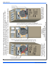
FIGURE 34: Double Horizontal Combustion Air Intake and Vent
Termination
FIGURE 35: Double Vertical Combustion Air Intake and Vent
Termination
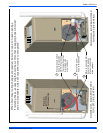
FIGURE 36: Downward Venting
VENT
2”
MIN.
COMBUSTIONAIR
MIN.
6”
16’ MAX
6” MIN.
6” MIN.
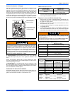
An optional plastic birdscreen is shipped in the loose parts bag with
every furnace. This may be installed in the intake collar to prevent any
small objects from entering the furnace.
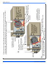
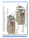
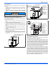
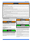
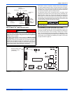
FIGURE 37: Direct Vent Air Intake Connection and Vent Connection
NOTICE
Connects to
collar on top
of burner box
Vent pipe cements
into socket just
above top panel
Or vent pipe may be
clamped into outlet
of drain coupling