


364861-UIM-H-0712
32 Johnson Controls Unitary Products
ADJUSTMENT OF MANIFOLD GAS PRESSURE &
INPUT RATE
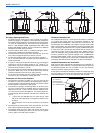
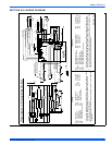
Inlet and manifold gas pressure may be measured by connecting the
“U” tube manometer to the gas valve with a piece of tubing. Follow the
appropriate section in the instructions below. Refer to Figure 40 for a
drawing of the locations of the pressure ports on the gas valve.
Turn gas off at the ball valve or gas cock on gas supply line
before the gas valve. Find the pressure ports on the gas
valve marked Out P and In P.
1. The manifold pressure must be taken at the port marked OUT P.
2. The gas line pressure must be taken at the port marked IN P.
3. Using a 3/32” (2.4 mm) Allen wrench, loosen the set screw by turn-
ing it 1 turn counter clockwise. DO NOT REMOVE THE SET
SCREW FROM THE PRESSURE PORT.
Read the inlet gas pressure
Connect the positive side of the manometer to the IN P Tap on the gas
valve. Do not connect any tubing to the negative side of the manometer,
as it will reference atmospheric pressure. Refer to Figure 41 for connec-
tion details.
1. Turn gas and electrical supplies on and follow the operating instruc-
tions to place the unit back in operation.
2. Once the correct gas inlet pressure has been established, see
Table 15, turn the gas valve to OFF and turn the electrical supply
switch to OFF; then remove the flexible tubing from the gas valve
pressure tap and tighten the pressure tap plug using the 3/32” (2.4
mm) Allen wrench.
3. Turn the electrical and gas supplies back on, and with the burners
in operation, check for gas leakage around the gas valve pressure
port for leakage using an approved non-corrosive gas leak detec-
tion fluid, or other non-flammable leak detection methods.
Read the manifold gas pressure
Connect the positive side of the manometer to the adapter previously
installed in the OUT P Tap on the gas valve. Do not connect any tubing
to the negative side of the manometer, as it will reference atmospheric
pressure. Refer to Figure 41 for connection details.
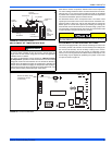
1. Refer to Figure 40 for location of pressure regulator adjustment cap
and adjustment screws on main gas valve.
2. Turn gas and electrical supplies on and follow the operating instruc-
tions to place the unit back in operation.
3. Adjust manifold pressure by adjusting gas valve regulator screw for
the appropriate gas per the following:
4. After the manifold pressure has been adjusted, re-calculate the fur-
nace input to make sure you have not exceeded the specified input
on the rating plate. Refer to “CALCULATING THE FURNACE
INPUT (NATURAL GAS)”.
5. Once the correct BTU (kW) input has been established, turn the
gas valve to OFF and turn the electrical supply switch to OFF; then
remove the flexible tubing from the gas valve pressure tap and
tighten the pressure tap plug using the 3/32” (2.4 mm) Allen
wrench.
6. Turn the electrical and gas supplies back on, and with the burners
in operation, check for gas leakage around the gas valve pressure
port for leakage using an approved non-corrosive gas leak detec-
tion fluid, or other non-flammable leak detection methods.
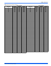
Table 15: Inlet Gas Pressure Range
INLET GAS PRESSURE RANGE
Natural Gas Propane (LP)
Minimum 4.5” w.c. (1.12 kPa) 8.0” w.c. (1.99 kPa)
Maximum 10.5” w.c. (2.61 kPa) 13.0” w.c. (3.24 kPa).
The inlet gas pressure operating range table specifies what the mini-
mum and maximum gas line pressures must be for the furnace to
operate safely. The gas line pressure MUST BE
a minimum of:
• 7” w.c. (1.74 kPA) for Natural Gas
• 11” w.c. (2.74 kPA) for Propane (LP) Gas
in order to obtain the BTU input specified on the rating plate and/or
the nominal manifold pressure specified in these instructions and on
the rating plate.
The cap for the pressure regulator must be removed entirely to gain
access to the adjustment screw. Loosening or tightening the cap does
not adjust the flow of gas.
The regulated outlet pressure has been calibrated at the factory.
Additional pressure adjustment should not be necessary. If adjust-
ment is necessary, set to the following specifications. After adjust-
ment, check for gas leakage.
Table 16: Nominal Manifold Pressure
NOMINAL MANIFOLD PRESSURE
Natural Gas 3.5" w.c. (0.87 kPa)
Propane (LP) Gas 10.0" w.c. (2.488 kPa)
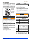
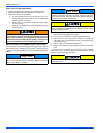
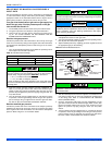
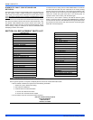
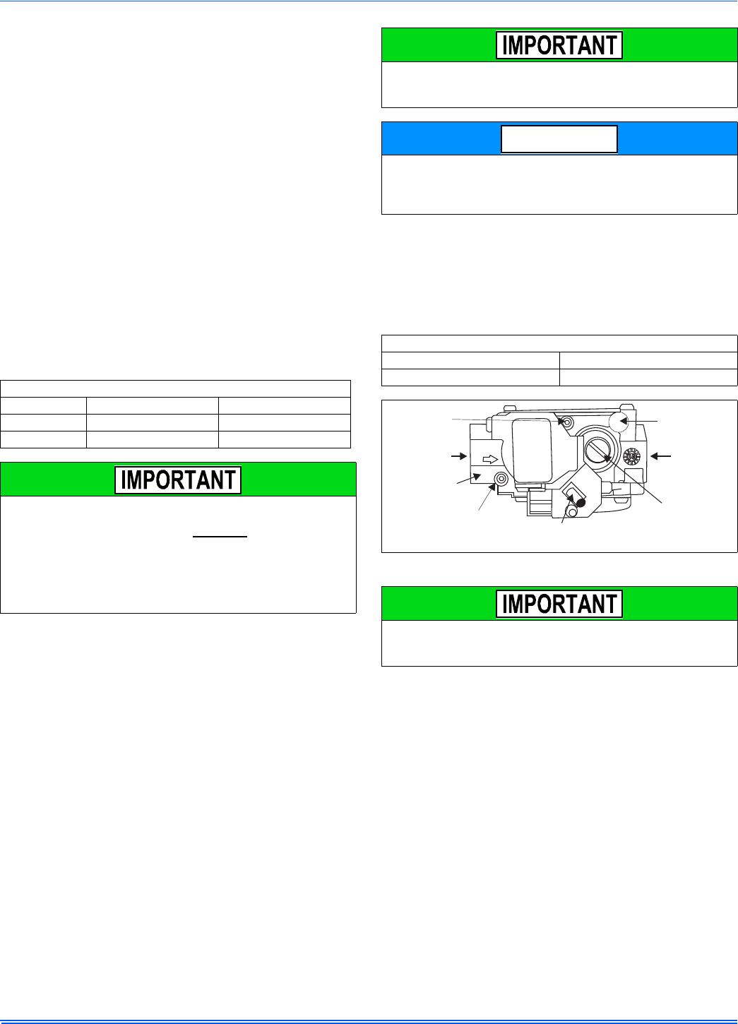
FIGURE 41: Gas Valve
If gas valve regulator is turned in (clockwise), manifold pressure is
increased. If screw is turned out (counterclockwise), manifold pres-
sure will decrease.
NOTICE
INLET
WRENCH
BOSS
INLET
PRESSURE
PORT
ON
OFF
ON/OFF SWITCH
(Shown in ON position)
MAIN REGULATOR
ADJUSTMENT
OUTLET
OUTLET
PRESSURE
PORT
VENT PORT