


364861-UIM-H-0712
Johnson Controls Unitary Products 25
VENT SYSTEM
This furnace is certified to be installed with one of two possible vent
configurations.
1. Horizontal vent system. This vent system can be installed com-
pletely horizontal or combinations of horizontal, vertical, or offset
using elbows.
2. Vertical vent system. This vent system can be installed completely
vertical or a combination of horizontal, vertical, or offset using
elbows.
VENT APPLICATIONS AND TERMINATION
When selecting the location for a combustion air / vent termination, the
following should be considered:
1. Observe all clearances listed in vent clearances in these instruc-
tions.
2. Termination should be positioned where vent vapors will not dam-
age plants or shrubs or air conditioning equipment.
3. Termination should be located where it will not be affected by wind
gusts, light snow, airborne leaves or allow recirculation of flue
gases.
4. Termination should be located where it will not be damaged or
exposed to flying stones, balls, etc.
5. Termination should be positioned where vent vapors are not objec-
tionable.
6. Horizontal portions of the vent system must slope upwards and be
supported to prevent sagging.
7. Direct vent systems must be installed so the vent and the combus-
tion air pipes terminate in the same atmospheric zone. Refer to Fig-
ures 32 or 33.
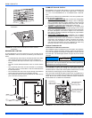
VENTING MULTIPLE UNITS
Multiple units can be installed in a space or structure as either a single
pipe configuration or a two-pipe configuration.
The combustion air side of the single pipe configuration shown in Figure
31 is referred to in these instructions as ambient combustion air supply.
Follow the instructions for ambient combustion air installations, paying
particular attention to the section on air source from inside the building.
The vent for a single pipe system must be installed as specified in the
venting section of these instructions with the vent terminating as shown
in Figure 31. Each furnace must have a separate vent pipe. Under NO
circumstances can the two vent pipes be tied together.
The combustion air side of the two-pipe configuration shown in Figure
32 can be installed so the combustion air pipe terminates as described
in outdoor combustion air or ventilated combustion air sections in these
instructions. Follow the instructions for outdoor combustion air or venti-
lated combustion air and the instructions for installing the vent system
with the vent terminating as shown in Figures 34 or 35. The two-pipe
system must have a separate combustion air pipe and a separate vent
pipe for each furnace. Under NO circumstances can the two combus-
tion air or vent pipes be tied together. The combustion air and vent
pipes must terminate in the same atmospheric zone.
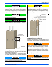
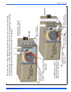
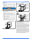
On 130K BTU models, there is no provision for the vent to exit
the top of the cabinet, the vent must always exit one of the sides.
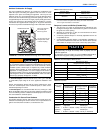
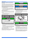
FIGURE 31: Termination Configuration - 1 Pipe
NOTICE
12” Min.
12” Min.
Maintain 12” minimum clearance
above highest anticipated snow level.
Maximum 24” above roof.
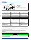
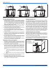
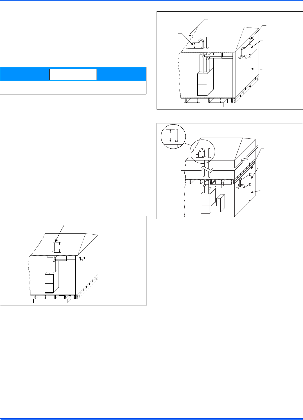
FIGURE 32: Termination Configuration - 2 Pipe
FIGURE 33: Termination Configuration - 2 Pipe Basement
Maintain 12” minimum
clearance above
highest anticipated
snow level.
12” vertical separation
between combustion air
intake and vent.
12” minimum
below overhang
12” minimum
separation between
bottom of
combustion air pipe
and bottom of vent.
Maintain 12”
minimum clearance
above highest
anticipated snow
level or grade,
whichever is higher.
12” MIN.
12” MIN.
OVERHANG
12” Minimum
below overhang
12” Minimum
separation between
bottom of
combustion air
intake and
bottom of vent
Maintain 12”
minimumclearance
above highest
anticipated snow
level or grade,
whichever is higher