


364861-UIM-H-0712
28 Johnson Controls Unitary Products
Air Supply Openings and Ducts
1. An opening may be used in lieu of a duct to provide to provide the
outside air supply to an appliance unless otherwise permitted by
the authority having jurisdiction. The opening shall be located within
12” (30.5 cm) horizontally from, the burner level of the appliance.
Refer to “AIR SOURCE FROM OUTDOORS AND VENT AND
SUPPLY AIR SAFETY CHECK” in these instructions for additional
information and safety check procedure.
2. The duct shall be either metal, or a material meeting the class 1
requirements of CAN4-S110 Standard for Air Ducts.
3. The duct shall be least the same cross-sectional area as the free
area of the air supply inlet opening to which it connects.
4. The duct shall terminate within 12” (30.5 cm) above, and within
24” (61 cm) horizontally from, the burner level of the appliance hav-
ing the largest input.
5. A square or rectangular shaped duct shall only be used when the
required free area of the supply opening is 9 in
2
(58.06 cm
2
) or
larger. When a square or rectangular duct is used, its small dimen-
sion shall not be less than 3” (7.6 cm).
6. An air inlet supply from outdoors shall be equipped with a means to
prevent the direct entry of rain and wind. Such means shall not
reduce the required free area of the air supply opening.
7. An air supply inlet opening from the outdoors shall be located not
less than 12” (30.5 cm) above the outside grade level.
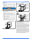
Combustion Air Source from Outdoors
1. Two permanent openings, one within 12” (30.5 cm) of the top and
one within 12” (30.5 cm) of bottom of the confined space, Two per-
manent openings, shall communicate directly or by means of ducts
with the outdoors, crawl spaces or attic spaces.
2. One permanent openings, commencing within 12” (30.5 cm) of the
top of the enclosure shall be permitted where the equipment has
clearances of at least 1” (2.54 cm) from the sides and back and 6”
(15.2 cm) from the front of the appliance. The opening shall com-
municate directly with the outdoors and shall have a minimum free
area of:
a. 1 square inch per 3000 BTU per hour (322 cm
2
per 0.879
kW) of the total input rating of all equipment located in the
enclosure.
b. Not less than the sum of all vent connectors in the confined
space.
3. The duct shall be least the same cross-sectional area as the free
area of the air supply inlet opening to which it connects.
4. The blocking effects of louvers, grilles and screens must be given
consideration in calculating free area. If the free area of a specific
louver or grille is not known. Refer to Table 11.
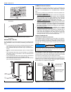
Ventilated Combustion Air
The ventilated attic space or a crawl space from which the combustion
air is taken must comply with the requirements specified in “AIR
SOURCE FROM OUTDOORS” in this instruction or in Section 5.3, Air
for Combustion and Ventilation of the National Fuel Gas Code, ANSI
Z223.1 (latest edition). This type installation requires two properly sized
pipes. One brings combustion air from a properly ventilated attic space
or crawl space and a second pipe that extends from the furnace vent
connection (top right of unit) to the exterior of the building. Refer to
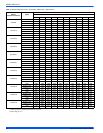
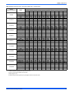
Table 7 for intake pipe sizing, allowable length and elbow usage. Follow
all notes, procedures and required materials in the "COMBUSTION
AIR/VENT PIPE SIZING" section in these instructions when installing
the combustion air pipe from the unit and into a ventilated attic space or
crawl space. DO NOT terminate vent pipe in an Attic or Crawl Space.
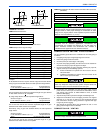
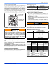
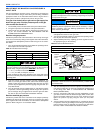
Ventilated Combustion Air Termination
Refer to Figure 39 for required attic termination for the combustion air
intake pipe. For attic termination, use two 90 elbows with the open end
in a downward position. Be sure to maintain 12” (30.5 cm) clearance
above any insulation, flooring or other material.
A crawl space combustion air installation consists of a straight pipe from
the PVC coupling on the burner box that extends into the crawl space
and terminates with a 1/4” (6.4 mm) mesh screen and no elbows.
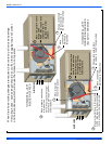
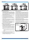
FIGURE 39: Outside and Ambient Combustion Air
Gable
Vent
Gas
Vent
Soffit
Vent
Ventilated
Attic
TopAbove
Insulation
Optional
Inlet (a)
Outlet
Air (a)
Ventilated
Crawl Space
Gas
Water
Heater
Furnace
Soffit
Vent
Gas
Water
Heater
Inlet
Air (a)
Inlet
Air (b)
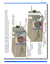
Furnace
Gas
Vent
Outlet
Air (a)
Outlet
Air (b)
Inlet
Air (a)
Inlet
Air (b)
Gas
Water
Heater
Furnace
Ventilated
Attic
TopAbove
Insulation
Gable
Vent
Gas
Vent
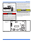
FIGURE 40: Attic and Crawl Space Combustion Air Termination
12” Min.
12” minimum
between bottom
of air intake and
any material below.