


364861-UIM-H-0712
30 Johnson Controls Unitary Products
IGNITION SYSTEM SEQUENCE
1. Turn the gas supply ON at external valve and main gas valve.
2. Set the thermostat above room temperature to call for heat.
3. System start-up will occur as follows:
a. The induced draft blower motor will start and come up to
speed. Shortly after inducer start-up, the hot surface igniter
will glow for about 17 seconds.
b. After this warm up, the ignition module will energize (open)
the main gas valve.
c. After flame is established, the supply air blower will start in
about 30 seconds.
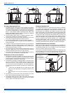
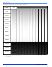
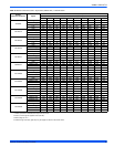
CALCULATING THE FURNACE INPUT (NAT. GAS)
Burner orifices are sized to provide proper input rate using natural gas
with a heating value of 1030 BTU/Ft
3
(38.4 MJ/m
3
). If the heating value
of your gas is significantly different, it may be necessary to replace the
orifices.
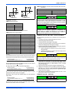
Verify natural gas input rate by clocking meter.
1. Turn off all other gas appliances and pilots.
2. Run furnace for a minimum of 3 minutes in heating operation.
3. Measure time (in sec) for gas meter to complete 1 revolution and
note reading. The 2 cubic feet dial provides a more accurate mea-
surement of gas flow.
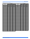
4. Refer to Table 14 for cubic feet of gas per hour.
5. Multiply cubic feet per hour by heating valve (BTU/cu ft) to obtain
input.
If clocked rate does not match the input rate from the unit nameplate.
follow steps in next section to adjust the manifold pressure. Repeat
steps 2 - 5 until correct input is achieved.
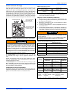
HOT SURFACE IGNITION SYSTEM
Do not attempt to light this furnace by hand (with a match or any
other means). There may be a potential shock hazard from the
components of the hot surface ignition system. The furnace can
only be lit automatically by its hot surface ignition system.
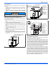
DO NOT set manifold pressure less than 3.2” w.c. or more than 3.8”
w.c. for natural gas at sea level. If manifold pressure is outside this
range, change main burner orifices.
NOTICE
If orifice hole appears damaged or it is suspected to have been
redrilled, check orifice hole with a numbered drill bit of correct size.
Never redrill an orifice. A burr-free and squarely aligned orifice hole is
essential for proper flame characteristics.
DO NOT bottom out gas valve regulator adjusting screw. This can
result in unregulated manifold pressure and result in excess overfire
and heat exchanger failures.
Be sure to relight any gas appliances that were turned off at the start
of this input check.
NOTICE