


364861-UIM-H-0712
18 Johnson Controls Unitary Products
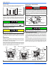
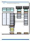
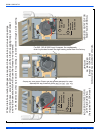
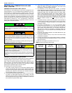
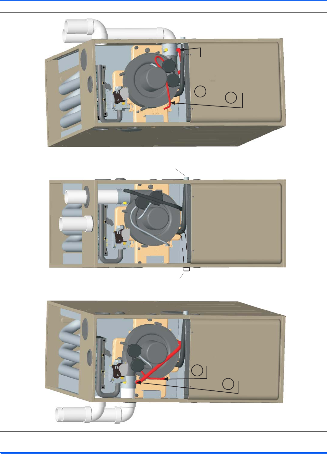
FIGURE 25: Upflow Configuration
INDUCER ROTATED FOR
LEFT SIDE VENTING
(As required for 130K model)
UPFLOW
AS RECEIVED
(Except for 130K Model)
INDUCER ROTATED FOR
RIGHT SIDE VENTING
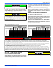
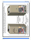
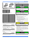
When drain hose routing changes are required, be sure to cap all un-used openings.
If rerouting hoses - excess length should be cut off so that no sagging loops will collect
and hold condensate, which will cause the furnace to not operate.
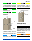
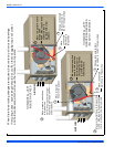
Shorten
pressure
switch hose
Re-route and
shorten
pressure
switch hose
Shorten
rain gutter
hose
Move rain
gutter hose
to this position
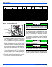
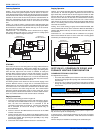
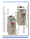
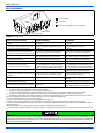
For 100, 120 & 130K input furnaces, the condensate
drain is plumbed toward the left casing outlet from the factory.
For 040, 060 & 080K input furnaces, the condensate
drain is plumbed toward the right casing outlet from the factory.
Condensate drain may exit cabinet on either side.
1
2
1
2
130 K Model does not have provisions for top venting, it must be vented through a side opening.