


364861-UIM-H-0712
10 Johnson Controls Unitary Products
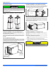
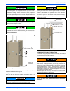
SIDE RETURN
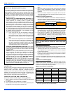
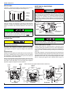
Locate the “L” shaped corner locators. These indicate the size of the cut-
out to be made in the furnace side panel. Refer to Figure 14.
Install the side filter rack following the instructions provided with that
accessory. If a filter(s) is provided at another location in the return air
system, the ductwork may be directly attached to the furnace side
panel.
HORIZONTAL APPLICATION
Horizontal Filters
Any branch duct (rectangular or round duct) attached to the plenum
must attach to the vertical plenum before the filter. The use of straps
and/or supports is required to support the weight of the external filter
box.
Downflow Filters
Downflow furnaces typically are installed with the filters located above
the furnace, extending into the return air plenum or duct. Any branch
duct (rectangular or round duct) attached to the plenum must attach to
the vertical plenum above the filter height.
Filter(s) may be located in the duct system external to the furnace using
an external duct filter box attached to the furnace plenum or at the end
of the duct in a return filter grille(s). The use of straps and/or supports is
required to support the weight of the external filter box.
SECTION IV: GAS PIPING
GAS SAFETY
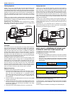
GAS PIPING INSTALLATION
Properly sized wrought iron, approved flexible or steel pipe must be
used when making gas connections to the unit. If local codes allow the
use of a flexible gas appliance connection, always use a new listed con-
nector. Do not use a connector that has previously serviced another gas
appliance.
Some utility companies or local codes require pipe sizes larger than the
minimum sizes listed in these instructions and in the codes. The furnace
rating plate and the instructions in this section specify the type of gas
approved for this furnace - only use those approved gases. The instal-
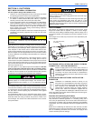
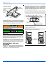
lation of a drip leg and ground union is required. Refer to Figure 16.
FIGURE 14: Side Return Cutout Markings
Some accessories such as electronic air cleaners and pleated media
may require a larger side opening. Follow the instructions supplied
with that accessory for side opening requirements. Do not
cut the
opening larger than the dimensions shown in Figure 13.
All filters and mounting provision must be field supplied. All installa-
tions must have a filter installed.
Front of
Furnace
Corner
Markings
Side of
Furnace
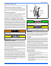
An overpressure protection device, such as a pressure regulator,
must be installed in the gas piping system upstream of the furnace
and must act to limit the downstream pressure to the gas valve so it
does not exceed 0.5 psig [14" w.c. (3.48 kPa)]. Pressures exceeding
0.5 psig [14” w.c. (3.48 kPa)] at the gas valve will cause damage to
the gas valve, resulting in a fire or explosion or cause damage to the
furnace or some of its components that will result in property damage
and loss of life.
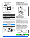
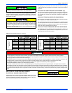
FIGURE 15: Gas Valve
Plan your gas supply before determining the correct gas pipe entry.
Use 90° service elbow(s), or short nipples and conventional 90°
elbow(s) to enter through the cabinet access holes.
DANGER
INLET
WRENCH
BOSS
INLET
PRESSURE
PORT
ON
OFF
ON/OFF SWITCH
(Shown in ON position)
MAIN REGULATOR
ADJUSTMENT
OUTLET
OUTLET
PRESSURE
PORT
VENT PORT
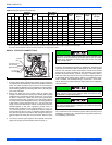
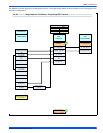
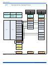
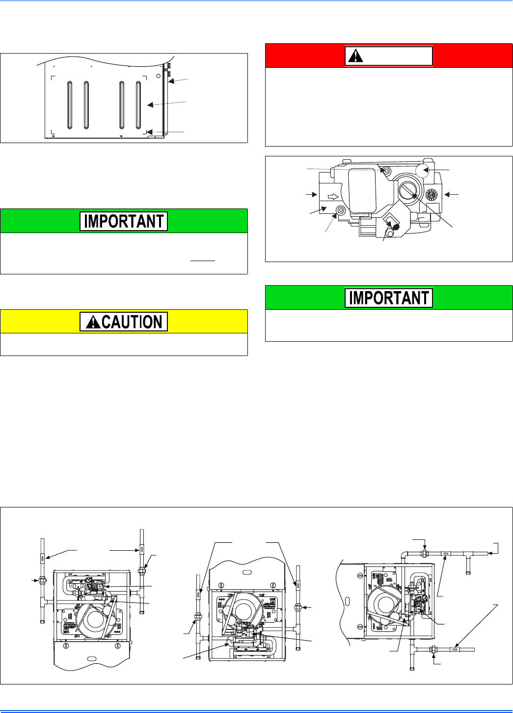
FIGURE 16: Gas Piping
Upflow
Downflow
Horizontal
External
Manual
Shut-off
Valve
External
Manual
Shut-off
Valve
External Manual
Shut-off Valve
To Gas
Supply
To Gas
Supply
To Gas
Supply
To Gas
Supply
To Gas
Supply
To Gas
Supply
Drip
Leg
Drip
Leg
Drip
Leg
Drip
Leg
Drip Leg
Drip
Gas
Pipe
Gas
Valve
Gas
Pipe
Gas
Valve
Gas
Pipe
Gas
Valve
Ground
Union
Ground
Union
Ground
Union
Ground
Union
Ground
Union
Ground
Union
NOTE: Ground Union maybe installed inside or outside unit.